| Previous Tutorial | Tutorial 38 | Next Tutorial | |||||
| STM32 DC Motor Speed PWM Control Examples & Driver (Library) | |||||||
| STM32 Course Home Page ???? | |||||||
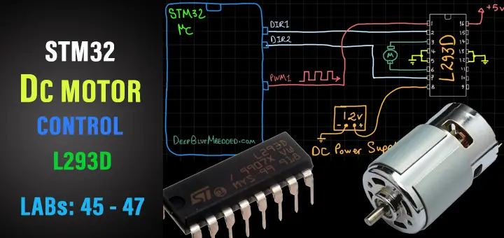
In this tutorial, we’ll be discussing DC motor speed control with STM32 PWM and L293D H-bridge motor driver. I’ll also show you the DC_MOTOR library (driver) that I’ve developed for STM32 microcontrollers and discuss how it works and how it’s been built in this way. And we’ll create 3 different example projects with STM32 uC and DC motors.
We’ll conclude this tutorial with some tests, measurements, and spot the light on potential improvements and features that you can make and add to this driver library code. But first of all, we’ll discuss how the DC Motor & L293D H-Bridge Driver work and how to control the DC motor’s speed and direction of rotation.
In this tutorial: 3 LABs
| LAB 45 | 1 DC Motor Speed Control With Tip122 Transistor – Testing Our Motor Library | ||||||
| LAB 46 | 1 DC Motor Control With L293D – Testing Our Motor Library | ||||||
| LAB 47 | 2 DC Motors Control With L293D – Testing Our Motor Library | ||||||
[toc]
Required Components For LABs
All the example code/LABs/projects in the course are going to be done using those boards below.
- Nucleo32-L432KC (ARM Cortex-M4 @ 80MHz) or (eBay)
- Blue Pill STM32-F103 (ARM Cortex-M3 @ 72MHz) or (eBay)
- ST-Link v2 Debugger or (eBay)
| QTY | Component Name | ???? Amazon.com | ???? eBay.com |
| 2 | BreadBoard | Amazon | eBay |
| 1 | LEDs Kit | Amazon Amazon | eBay |
| 1 | Resistors Kit | Amazon Amazon | eBay |
| 1 | Capacitors Kit | Amazon Amazon | eBay & eBay |
| 2 | Jumper Wires Pack | Amazon Amazon | eBay & eBay |
| 1 | 9v Battery or DC Power Supply | Amazon Amazon Amazon | eBay |
| 1 | Micro USB Cable | Amazon | eBay |
| 2 | Push Buttons | Amazon Amazon | eBay |
| 2 | DC Motor 12v | Amazon | eBay |
| 1 | DC Motor Driver (H-Bridge) | Amazon Amazon | eBay eBay |
| 1 | Potentiometers | Amazon Amazon | eBay |
★ Check The Full Course Complete Kit List
Some Extremely Useful Test Equipment For Troubleshooting:
- My Digital Storage Oscilloscope (DSO): Siglent SDS1104 (on Amazon.com) (on eBay)
- FeelTech DDS Function Generator: KKMoon FY6900 (on Amazon.com) (on eBay)
- Logic Analyzer (on Amazon.com) (on eBay)
Affiliate Disclosure: When you click on links in this section and make a purchase, this can result in this site earning a commission. Affiliate programs and affiliations include, but are not limited to, the eBay Partner Network (EPN) and Amazon.com.
DC Motor Control & L293D H-Bridge Driver
At the beginning of this tutorial, I’d like to make sure that all of you have the basic concepts behind DC motors operation and how we use PWM signals to control the speed of a DC motor. How an H-Bridge works and does the polarity-inversion to control the direction of the motor’s rotation. All of that and more are discussed in this previous tutorial about DC motor control with L293D driver. Check it out and come back to resume developing our DC motor driver library for STM32 microcontrollers.
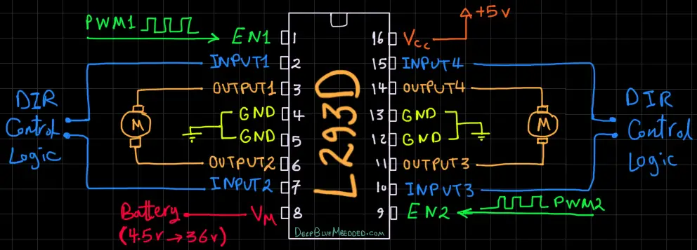
This file is the datasheet for the H-Bridge IC we’ll be using in this tutorial (L293D). Which is capable of delivering 0.6A of current per CH for 2 independent channels (2 motors). The motor supply voltage VM can be in the range from 4.5v up to 36v. You’ll also find the most important piece of information which is the pinout diagram and also a PCB layout example if you’re designing your own board, it’s going to be a good reference.
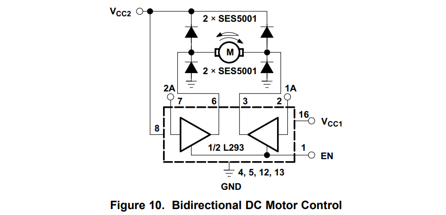
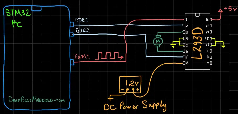
Near the end of the datasheet document, you’ll find some application examples. The most important one for us is the bidirectional motor control using one channel of the L293D IC. Here is the given figure for that configuration. And note that the fly-back diodes are not integrated within the IC. Therefore, we may include them in the wiring diagram later on. If not placed, you can still have everything running just as fine. As long as, your motor’s load is moderate. As it goes up, the IC will start heating up.
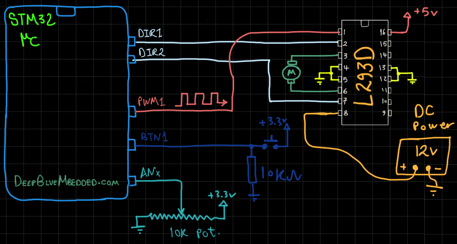
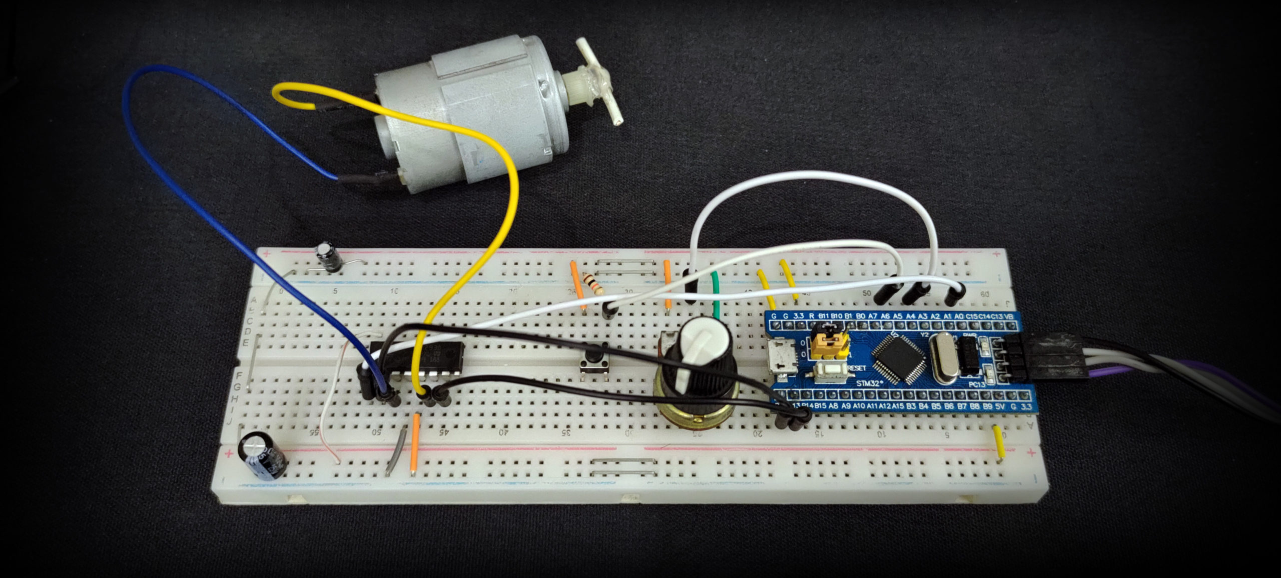
STM32 With L293D Motor Driver IC
Connection Diagram
Guidelines For Designing Our DC Motor Driver (Library)
Here are some guidelines and requirements that I did consider before designing the DC_MOTOR driver library with the current APIs. It can be improved in the future but for the beginning, it should be in line with the following:
- Has Configurable TIMERx and CHx for eachDC_MOTOR instance
- Multiple DC_MOTOR Instances Should Be Running Smoothly On the Same Timer With No Intervention (The PWM Frequency & Resolution Shall Be Shared Among Multiple Motors On The Same Timer).
- The User has full control over the PWM Resolution for motor speed control
- The PWM Frequency shall be an approximated value to what the user selects
STM32 Dc Motor Driver (Library)
The ECUAL DC_MOTOR driver is built for STM32 microcontrollers using one Timer channel in PWM mode. You’ll have to configure an instance of it and use the APIs to initialize, start, change speed, stop your motor, and that’s all. The code should be easily ported to any other STM32 microcontroller or reconfigured to use any Timer and PWM Channel that you want just as we’ll see in this section. And here is a link for the course’s repo, and you’ll find the DC_MOTOR driver in the ECUAL directory as usual.
DC MOTOR Driver Code Files
The DC_MOTOR driver consists of the following files:
|
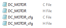 |
You’ll need only to modify the configuration files. The source code for this driver is found in (DC_MOTOR.c) and to use it you’ll include the header (DC_MOTOR.h). Nothing in the source code needs to be changed at all unless you need to add any extra features or customize the driver for your application’s needs. For today’s labs, we’ll only be changing the configuration files to build some test applications.
Therefore, I’ll write here the code listing for the DC_MOTOR.h & DC_MOTOR_cfg.c files.
DC_MOTOR.h File
|
1 2 3 4 5 6 7 8 9 10 11 12 13 14 15 16 17 18 19 20 21 22 23 24 25 26 27 28 29 30 31 32 33 34 35 36 |
#define HAL_TIM_MODULE_ENABLED #include "stm32f1xx_hal.h" // DC Motor Rotation Directions #define DIR_CW 0 #define DIR_CCW 1 // DC Motor PWM Properties #define DC_MOTOR_PWM_RES 10 #define DC_MOTOR_F_PWM 500 // The Number OF DC MOTORs To Be Used In The Project #define DC_MOTOR_UNITS 1 typedef struct { GPIO_TypeDef * DIR1_GPIO; GPIO_TypeDef * DIR2_GPIO; uint16_t DIR1_PIN; uint16_t DIR2_PIN; TIM_TypeDef* TIM_Instance; uint32_t PWM_TIM_CH; uint16_t TIM_CLK_MHz; uint32_t PWM_FREQ_Hz; uint8_t PWM_RES_BITS; }DC_MOTOR_CfgType; /*-----[ Prototypes For All Functions ]-----*/ void DC_MOTOR_Init(uint8_t au8_MOTOR_Instance); void DC_MOTOR_Start(uint8_t au8_MOTOR_Instance, uint8_t au8_DIR, uint16_t au16_SPEED); void DC_MOTOR_Set_Speed(uint8_t au8_MOTOR_Instance, uint16_t au16_SPEED); void DC_MOTOR_Set_Dir(uint8_t au8_MOTOR_Instance, uint8_t au8_DIR); void DC_MOTOR_Stop(uint8_t au8_MOTOR_Instance); uint32_t DC_MOTOR_Get_MaxFreq(uint8_t au8_MOTOR_Instance); |
If you’re willing to use multiple DC Motors, just adjust that number definition (DC_MOTOR_UNITS).
DC MOTOR Driver APIs
As you’ve seen in the DC_MOTOR.h file, the provided APIs do all the basic functionalities that you may need from a motor driver library.
DC_MOTOR_Init: initializes the required GPIO pins for direction control logic (DIR1 & DIR2), the associated Timer with the selected PWM channel. And sets the PWM resolution and frequency as configured by the user in the config file.
DC_MOTOR_Start: Sets the motor direction and speed to start the motor
DC_MOTOR_Set_Speed: Sets the speed of the motor by adjusting the PWM duty cycle
DC_MOTOR_Set_Dir: Sets the direction of rotation for the motor (CW or CCW)
DC_MOTOR_Stop: Stops the motor
DC_MOTOR_GET_MaxFreq: Returns the maximum operating frequency (in Hz) for the PWM channel at the selected PWM resolution in the config structure for that specific motor
The example LABs will put everything under test and you’ll see how and when to use each of these functions.
DC_MOTOR_cfg.c File
|
1 2 3 4 5 6 7 8 9 10 11 12 13 14 15 16 17 |
#include "../DC_MOTOR/DC_MOTOR.h" const DC_MOTOR_CfgType DC_MOTOR_CfgParam[DC_MOTOR_UNITS] = { // DC MOTOR 1 Configurations { GPIOB, GPIOB, GPIO_PIN_12, GPIO_PIN_13, TIM2, TIM_CHANNEL_1, 72, DC_MOTOR_F_PWM, DC_MOTOR_PWM_RES } }; |
I’ll discuss those configuration parameters in the next section down below.
Available Configurations For ECUAL DC Motor Driver
From the code above in DC_MOTOR.h & DC_MOTOR_cfg.c you can see that there are a handful of parameters in the configuration structure. The config structure will be used to assign the DIR1 & DIR2 GPIO pins, the associated TIMER peripheral you’ll be using (it can be TIM1, 2, and so on), the PWM_TIMER channel you’ll be using for the motor ENABLEx pin, the CLK speed in MHz for that specific TIMER module, the PWM frequency (in Hz), and finally the PWM resolution (in bits).
Typical Usage Application Example
Here is a typical usage application for this driver code in order to initialize & start a DC Motor, read an analog potentiometer with ADC. And use that reading to control the motor speed in the main loop of the system.
|
1 2 3 4 5 6 7 8 9 10 11 12 13 14 15 16 17 18 19 20 21 22 23 24 25 26 27 28 29 30 31 32 33 34 35 36 |
#include "main.h" #include "../ECUAL/DC_MOTOR/DC_MOTOR.h" #define DC_MOTOR1 0 ADC_HandleTypeDef hadc1; void SystemClock_Config(void); static void MX_GPIO_Init(void); static void MX_ADC1_Init(void); int main(void) { uint16_t AD_RES = 0; HAL_Init(); SystemClock_Config(); MX_GPIO_Init(); MX_ADC1_Init(); // Calibrate The ADC On Power-Up For Better Accuracy HAL_ADCEx_Calibration_Start(&hadc1); DC_MOTOR_Init(DC_MOTOR1); DC_MOTOR_Start(DC_MOTOR1, DIR_CW, 100); while (1) { // Start ADC Conversion HAL_ADC_Start(&hadc1); // Poll ADC1 Perihperal & TimeOut = 1mSec HAL_ADC_PollForConversion(&hadc1, 1); // Read The ADC Conversion Result & Map It To PWM DutyCycle AD_RES = HAL_ADC_GetValue(&hadc1); DC_MOTOR_Set_Speed(DC_MOTOR1, AD_RES>>2); HAL_Delay(1); } } |
PWM Resolution & Frequency Calculations
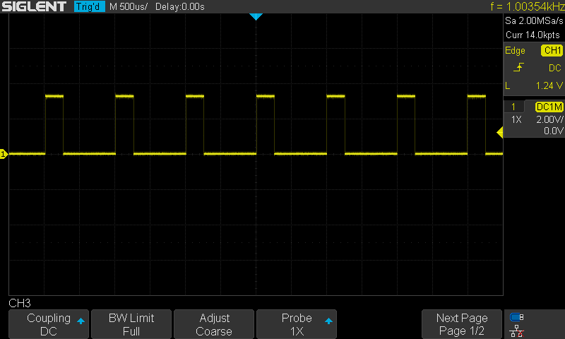
As I’ve stated earlier in this tutorial, my DC Motor driver (library) gives the user full control over the PWM signal’s resolution. And on the other hand, it does approximate the PWM frequency given by the user. In other words, for a configuration like this (desired resolution = 10-Bits, desired FPWM = 1kHz).
The actual PWM signal will have exactly 10Bits of resolution (0 up to 1023 speed levels) but the FPWM will be 1.003kHz as shown below. Not bad right? of course it’s not an exact value like the resolution but it’s just as fine as we won’t need that much FPWM accuracy in DC motor control applications.
This step is done at the initialization function for the DC Motor driver. Check the source code of the DC_MOTOR_Init function. And here is what I’m doing: first of all, we need to set the Timer’s Prescaler (PSC) and auto-reload register’s value (ARR) to control both PWM signal’s frequency and resolution.
This is the first formula for PWM resolution. We’ll solve for ARR given the user-defined resolution (in bits) and other parameters. We can easily solve for ARR value.
![]()
And now after knowing the ARR value, we can plug that into the FPWM equation and solve for PSC to find the approximate Prescaler value for the timer to get an FPWM that is as close as possible to the pre-defined value by the user.
![]()
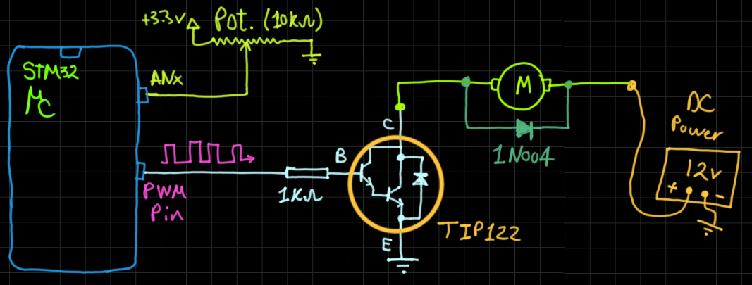
STM32 DC Motor Speed Control With Tip122 – LAB
| LAB Number | 45 |
| LAB Title | STM32 DC Motor Speed Control With Tip122 Transistor |
- Set up a new project as usual with a system clock @ 72MHz or whatever your uC board supports
- Enable TIMERx/CHx For PWM mode in CubeMX
- Enable Any ADC Channel in CubeMX
- Add the ECUAL / DC_MOTOR driver files to our project. As shown here
- Configure 1 DC_MOTOR instance in DC_MOTOR_cfg.c file
- Initialize the DC_MOTOR in the main application, start the DC Motor, read an analog potentiometer with ADC. And use that reading to control the motor speed in the main loop of the system.
And now, let’s build this system step-by-step
Step1: Open CubeMX & Create New Project
Step2: Choose The Target MCU & Double-Click Its Name
STM32F103C8 (the one I’ll be using) or any other STM32 part you’ve got
Step3: Go To The RCC Clock Configuration
Step4: Set The System Clock To Be 72MHz or whatever your uC board supports
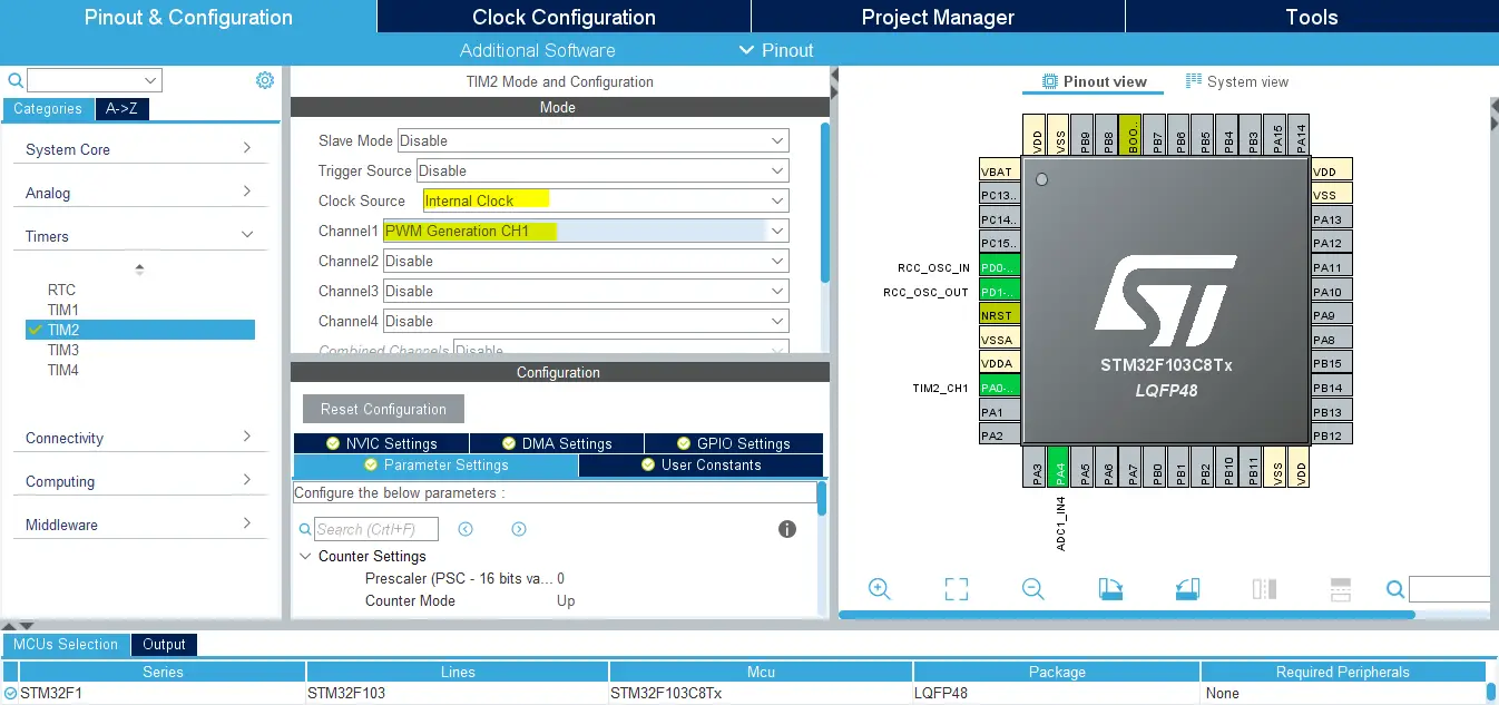
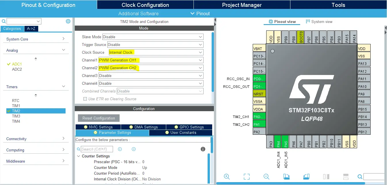
Step5: Enable The TIMERx/CHx PWM That You’ll be using For L293D ENABLEx Pin
We’ll have to do this step just to have the TIM_HAL files added to our project by CubeMX. And also it gives us a startup configuration for the PWM channel of that specific timer module as we’ll see hereafter. This is the best way to keep the code generic and portable to any STM32 microcontroller.
This step will result in adding a TIMER_Init function in our code by CubeMX, but we’ll remove it afterward as the DC_MOTOR_Init will handle that initialization procedure.
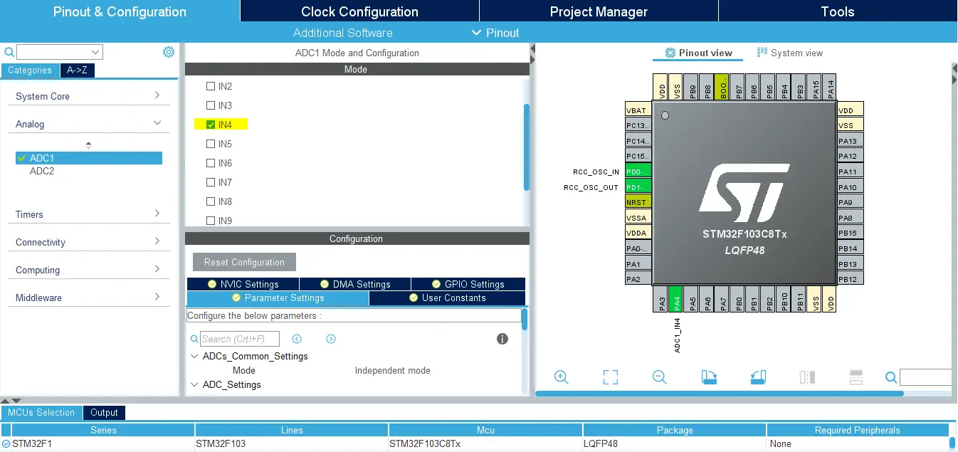
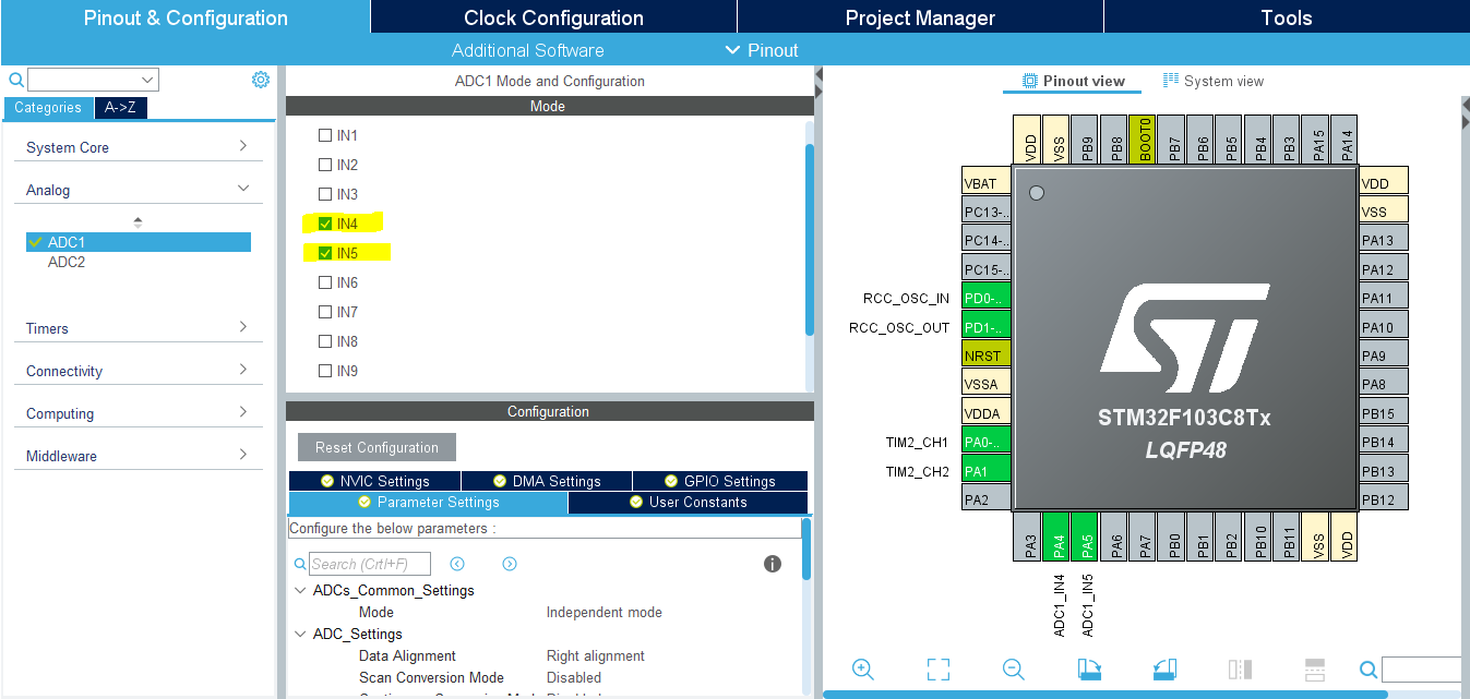
Step6: Enable The ADCx / CHx That You’ll Be Using For The Potentiometer
Step7: Generate The Initialization Code & Open The Project In Your IDE
Step8: Add the ECUAL/ DC_MOTOR driver files to your project
Follow This Tutorial which shows you How To Add Any ECUAL Driver To An STM32 Project step-by-step.

You basically right-click the project name in the IDE’s navigator and choose to create a new > source folder. And name it ECUAL and go to the GitHub repo, download the files and copy the “DC_MOTOR” folder and back to the IDE, right-click on the ECUAL and paste the library into it.
Now, we can start developing our application in the main.c source file.
Here Are The Drivers Configurations I Used For This LAB
DC_MOTOR_cfg.c File
|
1 2 3 4 5 6 7 8 9 10 11 12 13 14 15 |
const DC_MOTOR_CfgType DC_MOTOR_CfgParam[DC_MOTOR_UNITS] = { // DC MOTOR 1 Configurations { GPIOB, GPIOB, GPIO_PIN_12, GPIO_PIN_13, TIM2, TIM_CHANNEL_1, 72, DC_MOTOR_F_PWM, DC_MOTOR_PWM_RES } }; |
The DC_MOTOR_F_PWM and DC_MOTOR_PWM_RES are defined in the DC_MOTOR.h file. The FPWM is 500Hz and the resolution is 10-Bits.
Here is The Application Code For This LAB (main.c)
|
1 2 3 4 5 6 7 8 9 10 11 12 13 14 15 16 17 18 19 20 21 22 23 24 25 26 27 28 29 30 31 32 33 34 35 36 |
#include "main.h" #include "../ECUAL/DC_MOTOR/DC_MOTOR.h" #define DC_MOTOR1 0 ADC_HandleTypeDef hadc1; void SystemClock_Config(void); static void MX_GPIO_Init(void); static void MX_ADC1_Init(void); int main(void) { uint16_t AD_RES = 0; HAL_Init(); SystemClock_Config(); MX_GPIO_Init(); MX_ADC1_Init(); // Calibrate The ADC On Power-Up For Better Accuracy HAL_ADCEx_Calibration_Start(&hadc1); DC_MOTOR_Init(DC_MOTOR1); DC_MOTOR_Start(DC_MOTOR1, DIR_CW, 0); while (1) { // Start ADC Conversion HAL_ADC_Start(&hadc1); // Poll ADC1 Perihperal & TimeOut = 1mSec HAL_ADC_PollForConversion(&hadc1, 1); // Read The ADC Conversion Result & Map It To PWM DutyCycle AD_RES = HAL_ADC_GetValue(&hadc1); DC_MOTOR_Set_Speed(DC_MOTOR1, AD_RES>>2); HAL_Delay(1); } } |
Note that: I’ve deleted the auto-generated TIM2 initialization function and its parameter. Since our DC Motor library will handle that, we don’t need that function at all.
Do also look into the stm32f1xx_hal_msp.c file. You’ll find some initialization functions that get called in main.c at this line ( HAL_Init(); ),. While one of which is being used by my library for the DC Motor initialization routine. Which is the Timer PWM pin initialization.
|
1 2 3 4 5 6 7 8 9 10 11 12 13 14 15 |
void HAL_TIM_MspPostInit(TIM_HandleTypeDef* htim) { GPIO_InitTypeDef GPIO_InitStruct = {0}; if(htim->Instance==TIM2) { __HAL_RCC_GPIOA_CLK_ENABLE(); /**TIM2 GPIO Configuration PA0-WKUP ------> TIM2_CH1 */ GPIO_InitStruct.Pin = GPIO_PIN_0; GPIO_InitStruct.Mode = GPIO_MODE_AF_PP; GPIO_InitStruct.Speed = GPIO_SPEED_FREQ_LOW; HAL_GPIO_Init(GPIOA, &GPIO_InitStruct); } } |
As you can see, it does handle the PWM pin initialization for us for TIMER2 / CH1 pin. This can be hectic to do in our library init function ( DC_Motor_Init() ) in a generic way. So I’ve decided to use that function instead to keep the code more generic across all STM32 microcontrollers. Without having to figure out a way to find out which pin belongs to which timer’s channel and all that stuff.
Download The STM32 DC Motor Speed Control LAB45
The Result For This LAB Testing (Video)
Note that: this LAB is just a test for the basic functionality of our DC Motor Control library. Which is mainly built for L293D drivers and any H-Bridge that share the same control logic. That’s why the DIR1 & DIR2 pins are not useful in this LAB, despite the fact that they’re already initialized and reserved by the DC Motor library for DC_MOTOR1 structure.
STM32 DC Motor Control With L293D – LAB
| LAB Number | 46 |
| LAB Title | 1 DC Motor Control With L293D – Testing Our Motor Library |
- Set up a new project as usual with a system clock @ 72MHz or whatever your uC board supports
- Enable TIMERx/CHx For PWM mode in CubeMX
- Enable Any ADC Channel in CubeMX
- Add the ECUAL / DC_MOTOR driver files to our project. As shown here
- Add the ECUAL / BUTTONS driver files to our project
- Configure 1 DC_MOTOR instance in DC_MOTOR_cfg.c file
- Configure 1 BUTTON instance in BUTTONS_cfg.c file
- Initialize the BUTTON & DC_MOTOR in the main application, start the DC Motor, read an analog potentiometer with ADC. And use that reading to control the motor speed in the main loop of the system. Read the buttons and use it to flip the direction of motor rotation. Repeat!
And now, let’s build this system step-by-step
Step1: Open CubeMX & Create New Project
Step2: Choose The Target MCU & Double-Click Its Name
STM32F103C8 (the one I’ll be using) or any other STM32 part you’ve got
Step3: Go To The RCC Clock Configuration
Step4: Set The System Clock To Be 72MHz or whatever your uC board supports
Step5: Enable The TIMERx/CHx PWM That You’ll be using For L293D ENABLEx Pin
We’ll have to do this step just to have the TIM_HAL files added to our project by CubeMX. And also it gives us a startup configuration for the PWM channel of that specific timer module as we’ll see hereafter. This is the best way to keep the code generic and portable to any STM32 microcontroller.
This step will result in adding a TIMER_Init function in our code by CubeMX, but we’ll remove it afterward as the DC_MOTOR_Init will handle that initialization procedure.
Step6: Enable The ADCx / CHx That You’ll Be Using For The Potentiometer
Step7: Generate The Initialization Code & Open The Project In Your IDE
Step8: Add the ECUAL/ DC_MOTOR driver files to your project
Follow This Tutorial which shows you How To Add Any ECUAL Driver To An STM32 Project step-by-step.
You basically right-click the project name in the IDE’s navigator and choose to create a new > source folder. And name it ECUAL and go to the GitHub repo, download the files and copy the “DC_MOTOR” folder and back to the IDE, right-click on the ECUAL and paste the library into it.
Step9: Add the ECUAL/ BUTTONS driver files to your project
The same as the previous step
Step10: Add the MATH files to your project
Now, we can start developing our application in the main.c source file.
Here Are The Drivers Configurations I Used For This LAB
DC_MOTOR_cfg.c File
|
1 2 3 4 5 6 7 8 9 10 11 12 13 14 15 |
const DC_MOTOR_CfgType DC_MOTOR_CfgParam[DC_MOTOR_UNITS] = { // DC MOTOR 1 Configurations { GPIOB, GPIOB, GPIO_PIN_12, GPIO_PIN_13, TIM2, TIM_CHANNEL_1, 72, DC_MOTOR_F_PWM, DC_MOTOR_PWM_RES } }; |
The DC_MOTOR_F_PWM and DC_MOTOR_PWM_RES are defined in the DC_MOTOR.h file. The FPWM is 500Hz and the resolution is 10-Bits.
BUTTONS_cfg.c File
|
1 2 3 4 5 6 7 8 9 10 |
const BTN_CfgType BTN_CfgParam[BTN_UNITS] = { // Button 1 Configurations { GPIOA, GPIO_PIN_6, GPIO_NOPULL, BTNS_FILTER_ORDER } }; |
Here is The Application Code For This LAB (main.c)
|
1 2 3 4 5 6 7 8 9 10 11 12 13 14 15 16 17 18 19 20 21 22 23 24 25 26 27 28 29 30 31 32 33 34 35 36 37 38 39 40 41 42 43 44 45 46 47 48 49 50 51 52 53 54 55 56 57 58 59 60 |
#include "main.h" #include "../ECUAL/DC_MOTOR/DC_MOTOR.h" #include "../ECUAL/BUTTONS/BUTTONS.h" #define DC_MOTOR1 0 #define BTN1 0 ADC_HandleTypeDef hadc1; void SystemClock_Config(void); static void MX_GPIO_Init(void); static void MX_ADC1_Init(void); int main(void) { uint16_t AD_RES = 0; uint8_t BTNS_States[BTN_UNITS] = {BTN_RELEASED}; uint8_t MOTOR1_DIR = DIR_CW; uint8_t DIR_FLAG = 0; HAL_Init(); SystemClock_Config(); MX_GPIO_Init(); MX_ADC1_Init(); // Calibrate The ADC On Power-Up For Better Accuracy HAL_ADCEx_Calibration_Start(&hadc1); DC_MOTOR_Init(DC_MOTOR1); DC_MOTOR_Start(DC_MOTOR1, DIR_CW, 0); BTNs_Init(BTNS_States); while (1) { // Read Pot. ADC CH & Set Motor Speed HAL_ADC_Start(&hadc1); HAL_ADC_PollForConversion(&hadc1, 1); AD_RES = HAL_ADC_GetValue(&hadc1); DC_MOTOR_Set_Speed(DC_MOTOR1, AD_RES>>2); // Read BTN1 & Set Motor1 Direction BTN_Read(BTN1, &BTNS_States[BTN1]); if(BTNS_States[BTN1] == BTN_PRESSED) { if(DIR_FLAG == 0) { MOTOR1_DIR = DIR_CW; DIR_FLAG = 1; } else { MOTOR1_DIR = DIR_CCW; DIR_FLAG = 0; } DC_MOTOR_Set_Dir(DC_MOTOR1, MOTOR1_DIR); while(BTNS_States[BTN1] == BTN_PRESSED) { BTN_Read(BTN1, &BTNS_States[BTN1]); } } HAL_Delay(1); } } |
Note that: I’ve deleted the auto-generated TIM2 initialization function and its parameter. Since our DC Motor library will handle that, we don’t need that function at all.
Download The STM32 DC Motor Speed Control With L293D LAB46
The Result For This LAB Testing (Video)
STM32 Multi DC Motor Control L293D – LAB
| LAB Number | 47 |
| LAB Title | 2 DC Motors Control With L293D – Testing Our Motor Library |
- Set up a new project as usual with a system clock @ 72MHz or whatever your uC board supports
- Enable 2 TIMERx/CHx For PWM mode in CubeMX
- Enable Any 2 ADC Channels in CubeMX
- Add the ECUAL / DC_MOTOR driver files to our project. As shown here
- Add the ECUAL / BUTTONS driver files to our project
- Configure 2 DC_MOTOR instance in DC_MOTOR_cfg.c file
- Configure 2 BUTTON instance in BUTTONS_cfg.c file
- Initialize the BUTTONs & DC_MOTORs in the main application, start the DC Motors, read the analog potentiometers with ADC. And use that reading to control the 2 motor speeds in the main loop of the system. Read the buttons and use that signal to flip the direction of the 2 motors rotation. Repeat!
And now, let’s build this system step-by-step
Step1: Open CubeMX & Create New Project
Step2: Choose The Target MCU & Double-Click Its Name
STM32F103C8 (the one I’ll be using) or any other STM32 part you’ve got
Step3: Go To The RCC Clock Configuration
Step4: Set The System Clock To Be 72MHz or whatever your uC board supports
Step5: Enable The 2 TIMERx/CHx PWMs That You’ll be using For L293D ENABLE1, 2 Pins
We’ll have to do this step just to have the TIM_HAL files added to our project by CubeMX. And also it gives us a startup configuration for the PWM channel of that specific timer module as we’ll see hereafter. This is the best way to keep the code generic and portable to any STM32 microcontroller.
This step will result in adding a TIMER_Init function in our code by CubeMX, but we’ll remove it afterward as the DC_MOTOR_Init will handle that initialization procedure.
Step6: Enable The 2 ADCx / CHx That You’ll Be Using For The 2 Potentiometers
Step7: Generate The Initialization Code & Open The Project In Your IDE
Step8: Add the ECUAL/ DC_MOTOR driver files to your project
Follow This Tutorial which shows you How To Add Any ECUAL Driver To An STM32 Project step-by-step.
You basically right-click the project name in the IDE’s navigator and choose to create a new > source folder. And name it ECUAL and go to the GitHub repo, download the files and copy the “DC_MOTOR” folder and back to the IDE, right-click on the ECUAL and paste the library into it.
Step9: Add the ECUAL/ BUTTONS driver files to your project
The same as the previous step
Step10: Add the MATH files to your project
Now, we can start developing our application in the main.c source file.
Here Are The Drivers Configurations I Used For This LAB
DC_MOTOR_cfg.c File
|
1 2 3 4 5 6 7 8 9 10 11 12 13 14 15 16 17 18 19 20 21 22 23 24 25 26 27 |
const DC_MOTOR_CfgType DC_MOTOR_CfgParam[DC_MOTOR_UNITS] = { // DC MOTOR 1 Configurations { GPIOB, GPIOB, GPIO_PIN_12, GPIO_PIN_13, TIM2, TIM_CHANNEL_1, 72, DC_MOTOR_F_PWM, DC_MOTOR_PWM_RES }, // DC MOTOR 2 Configurations { GPIOB, GPIOB, GPIO_PIN_14, GPIO_PIN_15, TIM2, TIM_CHANNEL_2, 72, DC_MOTOR_F_PWM, DC_MOTOR_PWM_RES } }; |
The DC_MOTOR_F_PWM and DC_MOTOR_PWM_RES are defined in the DC_MOTOR.h file. The FPWM is 500Hz and the resolution is 10-Bits.
BUTTONS_cfg.c File
|
1 2 3 4 5 6 7 8 9 10 11 12 13 14 15 16 17 |
const BTN_CfgType BTN_CfgParam[BTN_UNITS] = { // Button 1 Configurations { GPIOA, GPIO_PIN_6, GPIO_NOPULL, BTNS_FILTER_ORDER }, // Button 2 Configurations { GPIOA, GPIO_PIN_7, GPIO_NOPULL, BTNS_FILTER_ORDER } }; |
Here is The Application Code For This LAB (main.c)
|
1 2 3 4 5 6 7 8 9 10 11 12 13 14 15 16 17 18 19 20 21 22 23 24 25 26 27 28 29 30 31 32 33 34 35 36 37 38 39 40 41 42 43 44 45 46 47 48 49 50 51 52 53 54 55 56 57 58 59 60 61 62 63 64 65 66 67 68 69 70 71 72 73 74 75 76 77 78 79 80 81 82 83 84 85 86 87 88 89 90 91 92 93 94 95 96 97 98 99 100 101 102 103 104 105 106 107 108 109 |
#include "main.h" #include "../ECUAL/DC_MOTOR/DC_MOTOR.h" #include "../ECUAL/BUTTONS/BUTTONS.h" #define DC_MOTOR1 0 #define DC_MOTOR2 1 #define BTN1 0 #define BTN2 1 ADC_HandleTypeDef hadc1; ADC_ChannelConfTypeDef sConfig = {0}; uint8_t BTNS_States[BTN_UNITS] = {BTN_RELEASED}; uint8_t MOTOR1_DIR = DIR_CW; uint8_t MOTOR2_DIR = DIR_CW; uint8_t DIR1_FLAG = 0; uint8_t DIR2_FLAG = 0; void SystemClock_Config(void); static void MX_GPIO_Init(void); static void MX_ADC1_Init(void); static void BUTTONS_HANDLER(void); static void Sys_Init(void); int main(void) { uint16_t AD_RES = 0; Sys_Init(); while (1) { // Read Pot. ADC CH4 & Set Motor1 Speed sConfig.Channel = ADC_CHANNEL_4; HAL_ADC_ConfigChannel(&hadc1, &sConfig); HAL_ADC_Start(&hadc1); HAL_ADC_PollForConversion(&hadc1, 1); AD_RES = HAL_ADC_GetValue(&hadc1); DC_MOTOR_Set_Speed(DC_MOTOR1, AD_RES>>2); // Read Pot. ADC CH5 & Set Motor2 Speed sConfig.Channel = ADC_CHANNEL_5; HAL_ADC_ConfigChannel(&hadc1, &sConfig); HAL_ADC_Start(&hadc1); HAL_ADC_PollForConversion(&hadc1, 1); AD_RES = HAL_ADC_GetValue(&hadc1); DC_MOTOR_Set_Speed(DC_MOTOR2, AD_RES>>2); // Read Buttons States & Handle Direction Logic BUTTONS_HANDLER(); HAL_Delay(1); } } static void Sys_Init(void) { HAL_Init(); SystemClock_Config(); MX_GPIO_Init(); MX_ADC1_Init(); // Calibrate The ADC On Power-Up For Better Accuracy HAL_ADCEx_Calibration_Start(&hadc1); DC_MOTOR_Init(DC_MOTOR1); DC_MOTOR_Init(DC_MOTOR2); DC_MOTOR_Start(DC_MOTOR1, DIR_CW, 0); DC_MOTOR_Start(DC_MOTOR2, DIR_CW, 0); BTNs_Init(BTNS_States); } static void BUTTONS_HANDLER(void) { // Read BTN1 & Set Motor1 Direction BTN_Read(BTN1, &BTNS_States[BTN1]); if(BTNS_States[BTN1] == BTN_PRESSED) { if(DIR1_FLAG == 0) { MOTOR1_DIR = DIR_CW; DIR1_FLAG = 1; } else { MOTOR1_DIR = DIR_CCW; DIR1_FLAG = 0; } DC_MOTOR_Set_Dir(DC_MOTOR1, MOTOR1_DIR); while(BTNS_States[BTN1] == BTN_PRESSED) { BTN_Read(BTN1, &BTNS_States[BTN1]); } } // Read BTN2 & Set Motor2 Direction BTN_Read(BTN2, &BTNS_States[BTN2]); if(BTNS_States[BTN2] == BTN_PRESSED) { if(DIR2_FLAG == 0) { MOTOR2_DIR = DIR_CW; DIR2_FLAG = 1; } else { MOTOR2_DIR = DIR_CCW; DIR2_FLAG = 0; } DC_MOTOR_Set_Dir(DC_MOTOR2, MOTOR2_DIR); while(BTNS_States[BTN2] == BTN_PRESSED) { BTN_Read(BTN2, &BTNS_States[BTN2]); } } } |
Note that: I’ve deleted the auto-generated TIM2 initialization function and its parameter. Since our DC Motor library will handle that, we don’t need that function at all.
Download The STM32 Multi DC Motor Control L293D Driver LAB47
The Result For This LAB Testing (Video)
Questions I Usually Get About DC Motor Control
PWM Frequency For DC Motor Speed Control?
This is one of the interesting questions that I’ve received a couple of times in the past and led us to a nice discussion about the matter. What you’d always hear regarding this topic is that FPWM should be not too low not too high for a reliable DC motor speed control.
And it can be really vague to decide which frequency is too low or high. But the commonly suggested values lie between 200Hz up to 2kHz or 5kHz. This is stated in many motor drivers’ ICs datasheets as the maximum switching frequency as well. While in other cases, the favored frequency can be up to 20kHz so as not to have any audible noise from the electronics side of the system. This can’t always be the case for all sorts of applications.
In fact, there is strong reasoning behind this being true. Which is a topic for a future article I’ll be publishing to show you my testing results and how to model a DC motor and take the parameters to MATLAB and simulate what’s going on and how FPWM affects the actual motor speed which can be weird to hear. Most of us at the beginning think that only the duty cycle controls the DC motor speed. However, it’ll turn out to be not exactly true, also the FPWM has a strong effect if not picked correctly as we’ll see.
PWM Resolution For DC Motor Speed Control?
Now, let’s see what value you should pick for the PWM resolution. It totally depends on the levels of control you want to have over the motor’s speed. And it should be the same as the ADC’s resolution for the potentiometer used for control.
If your ADC is 10-bits, there won’t be any reason to have a PWM resolution that goes beyond 10-bits as well. But generally speaking, having 10-bits of resolution is more than enough in most applications. And if you’re going to use my library as it is, you’ll have to keep in mind that the speed values you’re sending to the control function should be correct for the resolution you’ve selected. For example (Desired Resolution = 8bit, so the max speed is 255 & min is 0) and so on.
DC Motor Position Control
How to do position control using a DC Motor? well, this sounds like willing to create a servo motor. Basically, you’ll need to have some sort of feedback to tell the controller where is the DC Motor’s shaft. It can be physical contact with a rotary potentiometer or an optical encoder. I’ll try to include a similar tutorial for this in the future as well. But you can search this topic online to find more ideas and techniques to achieve servo motor control using DC motors.
Did you find this helpful? If yes, please consider supporting this work and sharing these tutorials!
Stay tuned for the upcoming tutorials and don’t forget to SHARE these tutorials. And consider SUPPORTING this work to keep publishing free content just like this!
| Previous Tutorial | Tutorial 38 | Next Tutorial | |||||
Hello Mr. Magdy,
would you some day make a project with SX1278