| Previous Tutorial | Tutorial 30 | Next Tutorial | |||||
| STM32 PWM-To-DAC Waveform Generation With DMA | |||||||
| STM32 Course Home Page ???? | |||||||
In this LAB, we’ll discuss how to generate analog waveforms like (sine, sawtooth, triangular, etc) using STM32 PWM As a DAC with DMA transfer. And how to control the output waveform frequency. And also how to generate the waveform lookup table points for each function using MATLAB. Let’s get right into it!
[toc]
Required Components For LABs
All the example code/LABs/projects in the course are going to be done using those boards below.
- Nucleo32-L432KC (ARM Cortex-M4 @ 80MHz) or (eBay)
- Blue Pill STM32-F103 (ARM Cortex-M3 @ 72MHz) or (eBay)
- ST-Link v2 Debugger or (eBay)
| QTY | Component Name | ???? Amazon.com | ???? eBay.com |
| 2 | BreadBoard | Amazon | eBay |
| 1 | LEDs Kit | Amazon Amazon | eBay |
| 1 | Resistors Kit | Amazon Amazon | eBay |
| 1 | Capacitors Kit | Amazon Amazon | eBay & eBay |
| 2 | Jumper Wires Pack | Amazon Amazon | eBay & eBay |
| 1 | 9v Battery or DC Power Supply | Amazon Amazon Amazon | eBay |
| 1 | Micro USB Cable | Amazon | eBay |
| 1 | Push Buttons | Amazon Amazon | eBay |
★ Check The Full Course Complete Kit List
Some Extremely Useful Test Equipment For Troubleshooting:
- My Digital Storage Oscilloscope (DSO): Siglent SDS1104 (on Amazon.com) (on eBay)
- FeelTech DDS Function Generator: KKMoon FY6900 (on Amazon.com) (on eBay)
- Logic Analyzer (on Amazon.com) (on eBay)
Affiliate Disclosure: When you click on links in this section and make a purchase, this can result in this site earning a commission. Affiliate programs and affiliations include, but are not limited to, the eBay Partner Network (EPN) and Amazon.com.
STM32 PWM As A DAC For Waveform Generation
As we’ve seen in the previous tutorial (STM32 PWM As A DAC), the PWM peripheral in STM32 microcontrollers can be used as a DAC to output analog voltage that corresponds to the duty cycle of the PWM signal. Hence, generating analog waveforms is nothing more than writing out the waveform data points from somewhere in the memory to the PWM duty cycle control register (CCRx). This process can be divided into two major steps:
Step1: Generating The Lookup Table
The lookup table is an array of unsigned integer values that represents the sample points of a specific waveform for a complete cycle (from 0 to 2π). The length of the lookup table is denoted as Ns or the number of sample points per complete cycle. The more sample points per cycle, the better the output waveform.
We’ll be using MATLAB script for generating the sample points lookup table for various waveforms as we’ll see in the next section. Afterward, we’ll copy it to our code so that the Wave_LUT[NS] array is ready to be transferred to the DAC output.
Step2: Moving The Data To The DAC Output (PWM Duty Cycle)
There exist a number of different ways in order to transfer some data points from the memory to the PWM duty cycle control register. The first of which is by using the CPU power itself. We can loop through the lookup table and send the waveform sample points one by one to the CCRx register. However, this method is so bad for loading the CPU and consuming 100% of its time. Moreover, any CPU interrupts or going to handle other tasks will distort the timing of the output signal for the PWM-To-DAC system. This is obviously not a very good idea, despite the fact that it works (in very limited situations). And in this case, the output waveform’s frequency is controlled by changing the delay period (x).
|
1 2 3 4 5 |
while(1) { TIMx->CCRx = Wave_LUT[i++]; DWT_Delay_us(x); } |
Another way is to use Timer interrupts to periodically fire an interrupt signal so that the CPU can transfer the data points to the CCRx in a periodic manner. However, it’s a more efficient way than the previous one. But it still requires a lot of CPU intervention, especially when a high sampling rate is required. Sometimes it can be unachievable at all or achievable but loads the CPU by 60% or more. Which is also not a very good idea. Despite the fact that it does work and better than the previous method.
Lastly, we can use the DMA & Timer to periodically trigger the DMA unit so that it moves a sample data point from the lookup table stored in memory to the PWM duty cycle control register (CCRx). Each time the timer trigger event occurs, the DMA transfers a data point from the table to the CCRx and increments the memory pointer to move the next data point in the next trigger event. This method is the best way to achieve the task without any CPU intervention.
The DMA can also be configured to operate in the circular mode so that it wraps around the lookup table every time it reaches the end of the table. Therefore, no action is required by the CPU at all. And this is what we’re going to implement in this LAB today.
Generating The Waveform Lookup Table
There are many ways to generate a lookup table for any waveform you want. One of which is calculating the data points in the runtime using the CPU of the target itself. You power up the system, the CPU starts calculating the sine function points for example, and store them in the Wave_LUT[] array and use it afterward.
You can also use an online calculator like This Sine Lookup Table Generator Tool. Define the number of points you want and the maximum amplitude (defined by your DAC’s resolution), and generate the table. Copy and paste it into your code and you’re good to go.
Alternatively, you can use a MATLAB script to generate and print the waveform sample points. You can configure the script below to set the required sample points number (Ns) and give it an offset from 0 in case you want that. And also the resolution of the DAC in your system (in bits).
Here is the MATLAB script that generates the lookup table for you.
|
1 2 3 4 5 6 7 8 9 10 11 12 13 14 15 16 17 18 19 |
clear; clc; % Clear The Previous Points Ns = 128; % Set The Number of Sample Points RES = 10; % Set The DAC Resolution OFFSET = 0; % Set An Offset Value For The DAC Output %------------[ Calculate The Sample Points ]------------- T = 0:((2*pi/(Ns-1))):(2*pi); Y = sin(T); Y = Y + 1; Y = Y*((2^RES-1)-2*OFFSET)/(2+OFFSET); Y = round(Y); plot(T, Y); grid %--------------[ Print The Sample Points ]--------------- fprintf('%d, %d, %d, %d, %d, %d, %d, %d, %d, %d, %d, %d, %d, %d, %d, \n', Y); %-------------------[ Other Examples To Try ]------------------- % Y = diric(T, 13); % Periodic Sinc % Y = sawtooth(T) % Sawtooth % Y = sawtooth(T, 0.5); % Triangular |
The waveform can be changed by adjusting the function calculation line. Three examples are commented at the end of the script. A periodic sinc function, sawtooth, and a triangular waveform.
PWM-DAC DMA Sine Waveform Generation
Now, we’ve got the waveform lookup table and also decided to use the DMA triggered by a timer in order to move the data points from the lookup table to the PWM duty cycle register. The question is, how to calculate & control the output waveform frequency?
Let’s say we’ve generated a sinewave lookup table with 128 sample points (Ns), and configured Timer2 so it triggers the DMA transfer to the PWM duty cycle. What would be the output sine wave frequency?
Here are the formulas to be used
![]()
Where FCLK is the frequency of the clock used by your timer module, PSC is the Prescaler, and ARR is the value of the auto-reload register.
![]()
Where Ns is the sample points number in the lookup table.
For example, let’s assume the following settings:
The FCLK is 80MHz, the PSC is 0, ARR is 1000, and the sine lookup table has 128 sample points. What would be the output sine wave frequency?
TriggerFrequency = 80MHz / 1001 = 79920.08
Output Sinewave Frequency = TriggerFrequency / 128 = 624.37 Hz
For example, let’s assume the following settings:
an output sine wave is required to be generated with a frequency of 1kHz
The FCLK is 72MHz, and the sine lookup table has 128 sample points. What would be the timer configurations?
Output SineWave Frequency = Trigger frequency / 128
1KHz = TriggerFrequency / 128
TriggerFrequency = 128KHz
TriggerFrequency = 72MHz / (PSC+1)(ARR+1)
128KHz = 72MHz / (PSC+1)(ARR+1)
let’s choose PSC = 0, and solve for ARR
ARR will therefore be ARR = 561.5
Design STM32 PWM As A DAC For Wave Gen. System
As we’ve learned in the previous tutorial (STM32 PWM As A DAC), in order to design a PWM-To-DAC system you’ll have to go through the following steps one by one. I’ll restate them again for today’s LAB so that everything is clear when we start implementing the system.
1- Decide On The Required Resolution
Using the PWM-To-DAC technique implies the following fact “PWM’s resolution dictates the resulting DAC’s resolution”. In other words, the final DAC’s resolution is defined by the PWM’s resolution it’s the same value. Therefore, we’ve to decide on the required resolution for the final DAC so that we can pick the PWM’s frequency that guarantees to achieve the required resolution.
In today’s LAB, we’ll stick to a 10-Bit resolution. This means the resulting DAC we’ll be building using the PWM technique will be also 10-Bit in resolution.
2- PWM Frequency Selection
A rule of thumb is to choose the FPWM to be some order of magnitudes larger than the desired output signal’s frequency FBW. The larger the factor k the better.
![]()
And also keep in mind that raising the FPWM will degrade the final DAC’s resolution. As you can see from the formula down below. This indicates that raising the FPWM will decrease its resolution at any value for timer clock FCLK, and therefore the DAC’s resolution decreases as well.

The formula to be used in configuring the timer module in PWM mode to control the PWM output frequency.
![]()
In this LAB, we’ll generate 1kHz waveforms and up to 5kHz. And in order to guarantee a resolution of 10-Bits, using the formulas above we can say the following
For 10-Bit resolution, FPWM should be no more than 70.312kHz
And as we’re going to generate signals from 1 up to 5kHz. Then the FBW is maybe 15 times less than the FPWM and we’re sticking to the guidelines with no problem.
3- RC LPF Design
This step is the most critical step in the design process. As it defines the dynamic characteristics of the resulting DAC system at the end. The LPF filter introduces some delay due to the time constant that can limit the DAC’s ability to swing very quickly to follow a specific waveform pattern.
We need to filter out all the PWM signal frequency components and leave out the FBW of the signal to be generated. As shown in the diagram below, we want to eliminate the high-frequency components and leave only the low-frequency sine wave.
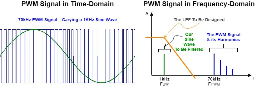
The LPF should be designed so as to pass the frequency of the desired signal FBW while blocking the FPWM harmonics. And the following formula is used for this.
![]()
Choose the resistor R depending on the GPIO pin output driving capability and solve for C to find the capacitor value. And you can calculate the attenuation using the following formula. And if the attenuation is not sufficient, you’ll have to increase the k factor.
![]()
you can customize the filter’s design to meet your application’s criteria. You can use a high order filter that has a sharper roll-off so it filters out the PWM signal in a stronger manner.

STM32 PWM-To-DAC WaveForm Generator – LAB25
| LAB Number | 25 |
| LAB Title | STM32 PWM As A DAC With DMA Waveform Generation |
- Set up a new project as usual with system clock @ 72MHz
- Set up timer2 CH1 PWM
- Use the provided MATLAB script to generate lookup tables to be used for this LAB
- Setup timer4 CH1 to be the trigger source for DMA1 unit
- Setup DMA1 to move the LUT data points from memory to Tim2->CCR1 in circular mode
- Generate a 1KHz sine waveform. Change the lookup table data to make it sawtooth, triangular functions
- Change the output signal frequency using the given formula in code to make the output sine wave’s frequency 5KHz
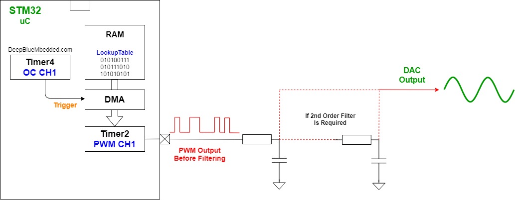
Here Is A Block Diagram For The System We’ll Build
And now, let’s build this system step-by-step
Step1: Open CubeMX & Create New Project
Step2: Choose The Target MCU & Double-Click Its Name
STM32F103C8
Step3: Go To The Clock Configuration
Step4: Set The System Clock To Be 72MHz
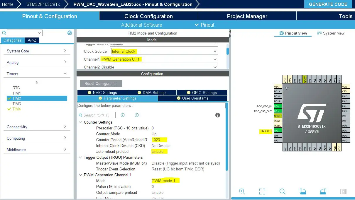
Step5: Setup Timer2 In PWM Mode on CH1 With ARR=1023
The ARR is set to 1023 in order to have a 10-Bit resolution PWM signal with a frequency of 70.3kHz
As we’ve previously calculated in this tutorial
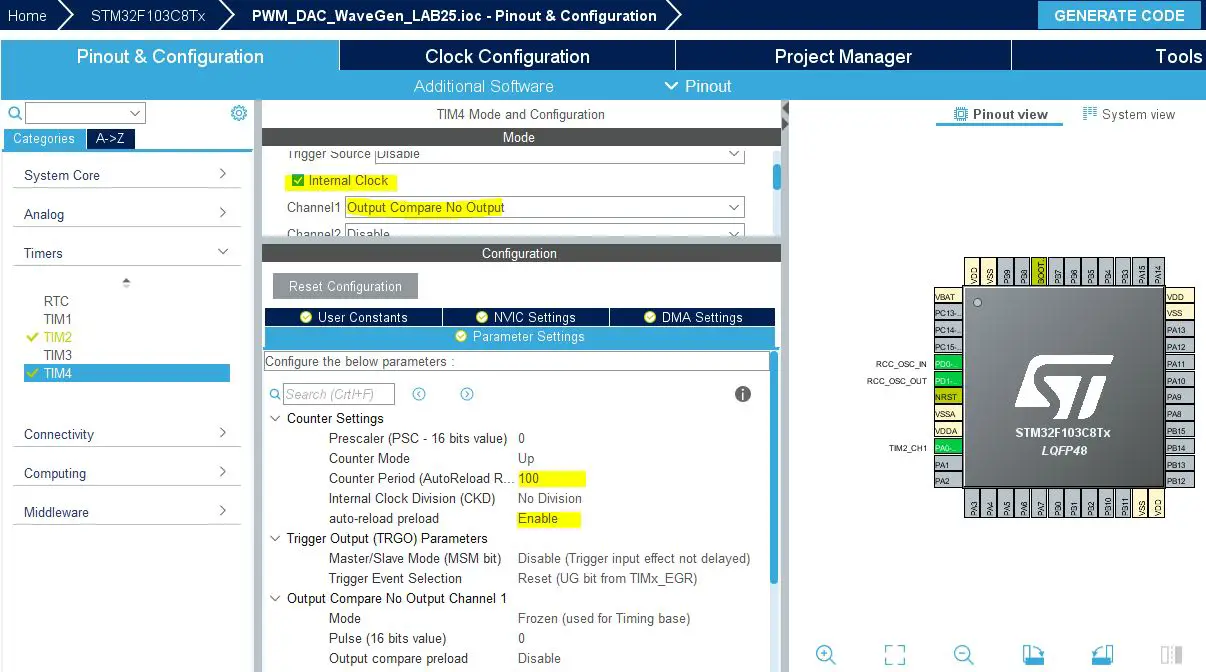
Step6: Setup Timer4 To Operate in OC Mode On CH1
The value of the ARR register here doesn’t matter so much. Write 100 or let it as 0. The application code calculates the value for ARR and overwrites it in order to achieve the required signal frequency defined by you at the beginning of the code.
|
1 2 |
#define TIM4CLK 72000000 #define F_SIGNAL 5000 |
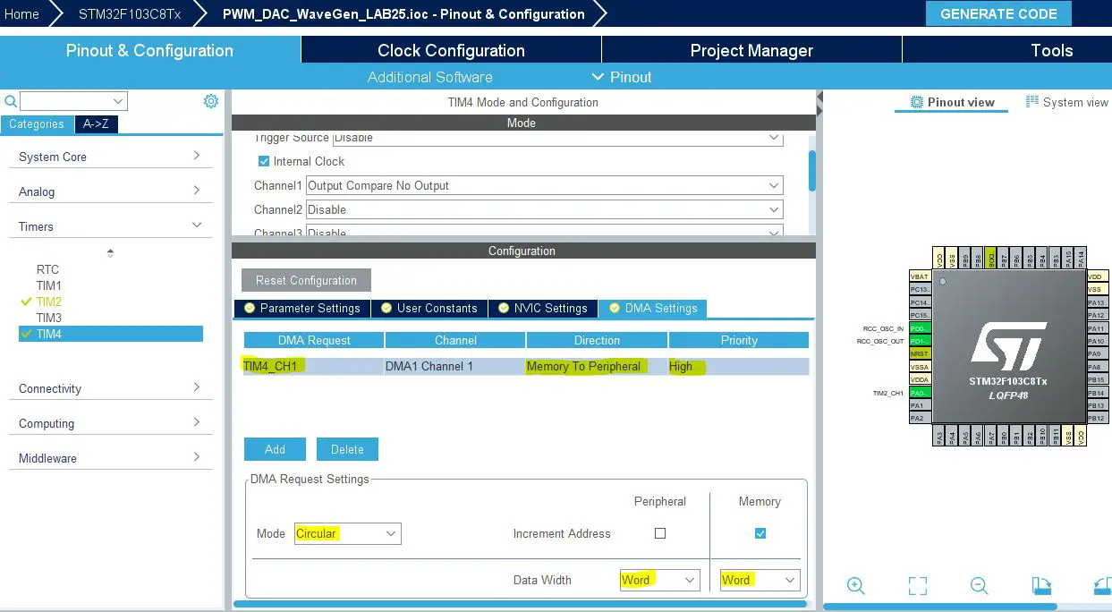
Step7: Now, Enable Timer4 DMA & Add a Channel To Do The Memory-To-Peripheral Transfer
Step8: Generate The Initialization Code & Open The Project In Your IDE
Here is The Application Code For This LAB (main.c)
|
1 2 3 4 5 6 7 8 9 10 11 12 13 14 15 16 17 18 19 20 21 22 23 24 25 26 27 28 29 30 31 32 33 34 35 36 37 38 39 40 41 42 43 44 45 46 47 48 49 |
#include "main.h" #define NS 128 #define TIM4CLK 72000000 #define F_SIGNAL 1000 uint32_t Wave_LUT[NS] = { 512, 537, 562, 587, 612, 637, 661, 685, 709, 732, 754, 776, 798, 818, 838, 857, 875, 893, 909, 925, 939, 952, 965, 976, 986, 995, 1002, 1009, 1014, 1018, 1021, 1023, 1023, 1022, 1020, 1016, 1012, 1006, 999, 990, 981, 970, 959, 946, 932, 917, 901, 884, 866, 848, 828, 808, 787, 765, 743, 720, 697, 673, 649, 624, 600, 575, 549, 524, 499, 474, 448, 423, 399, 374, 350, 326, 303, 280, 258, 236, 215, 195, 175, 157, 139, 122, 106, 91, 77, 64, 53, 42, 33, 24, 17, 11, 7, 3, 1, 0, 0, 2, 5, 9, 14, 21, 28, 37, 47, 58, 71, 84, 98, 114, 130, 148, 166, 185, 205, 225, 247, 269, 291, 314, 338, 362, 386, 411, 436, 461, 486, 511 }; TIM_HandleTypeDef htim2; TIM_HandleTypeDef htim4; DMA_HandleTypeDef hdma_tim4_ch1; uint32_t DestAddress = (uint32_t) &(TIM2->CCR1); uint32_t TIM4_Ticks = TIM4CLK / (NS * F_SIGNAL); void SystemClock_Config(void); static void MX_GPIO_Init(void); static void MX_DMA_Init(void); static void MX_TIM2_Init(void); static void MX_TIM4_Init(void); int main(void) { HAL_Init(); SystemClock_Config(); MX_GPIO_Init(); MX_DMA_Init(); MX_TIM2_Init(); MX_TIM4_Init(); HAL_TIM_PWM_Start(&htim2, TIM_CHANNEL_1); HAL_TIM_OC_Start(&htim4, TIM_CHANNEL_1); HAL_DMA_Start_IT(&hdma_tim4_ch1, (uint32_t)Wave_LUT, DestAddress, NS); __HAL_TIM_ENABLE_DMA(&htim4, TIM_DMA_CC1); while (1) { } } |
It’s important to edit the TIM4 initialization function. Here is the code for it, and notice that I’m overwriting the ARR register value in order to achieve the desired output signal’s frequency defined at the beginning of the above code.
|
1 2 3 4 5 6 7 8 9 10 11 12 13 14 15 16 17 18 19 20 21 22 23 24 25 26 27 28 29 30 31 32 33 34 35 36 37 38 39 40 41 42 43 44 45 46 47 48 49 50 51 52 |
static void MX_TIM4_Init(void) { /* USER CODE BEGIN TIM4_Init 0 */ /* USER CODE END TIM4_Init 0 */ TIM_ClockConfigTypeDef sClockSourceConfig = {0}; TIM_MasterConfigTypeDef sMasterConfig = {0}; TIM_OC_InitTypeDef sConfigOC = {0}; /* USER CODE BEGIN TIM4_Init 1 */ /* USER CODE END TIM4_Init 1 */ htim4.Instance = TIM4; htim4.Init.Prescaler = 0; htim4.Init.CounterMode = TIM_COUNTERMODE_UP; htim4.Init.Period = TIM4_Ticks-1; // <---- This Line htim4.Init.ClockDivision = TIM_CLOCKDIVISION_DIV1; htim4.Init.AutoReloadPreload = TIM_AUTORELOAD_PRELOAD_ENABLE; if (HAL_TIM_Base_Init(&htim4) != HAL_OK) { Error_Handler(); } sClockSourceConfig.ClockSource = TIM_CLOCKSOURCE_INTERNAL; if (HAL_TIM_ConfigClockSource(&htim4, &sClockSourceConfig) != HAL_OK) { Error_Handler(); } if (HAL_TIM_OC_Init(&htim4) != HAL_OK) { Error_Handler(); } sMasterConfig.MasterOutputTrigger = TIM_TRGO_RESET; sMasterConfig.MasterSlaveMode = TIM_MASTERSLAVEMODE_DISABLE; if (HAL_TIMEx_MasterConfigSynchronization(&htim4, &sMasterConfig) != HAL_OK) { Error_Handler(); } sConfigOC.OCMode = TIM_OCMODE_TIMING; sConfigOC.Pulse = 0; sConfigOC.OCPolarity = TIM_OCPOLARITY_HIGH; sConfigOC.OCFastMode = TIM_OCFAST_DISABLE; if (HAL_TIM_OC_ConfigChannel(&htim4, &sConfigOC, TIM_CHANNEL_1) != HAL_OK) { Error_Handler(); } /* USER CODE BEGIN TIM4_Init 2 */ /* USER CODE END TIM4_Init 2 */ } |
Download The STM32 PWM-To-DAC With DMA WaveForm Generator LAB25
The Result For This LAB Testing On My DSO
Here is the result for the first test (sine wave @ 1KHz)

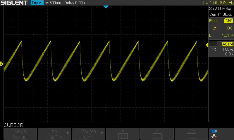
Here is the result for the 2nd test (sawtooth wave @ 1KHz)
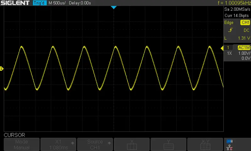
Here is the result for the 3rd test (triangular wave @ 1KHz)
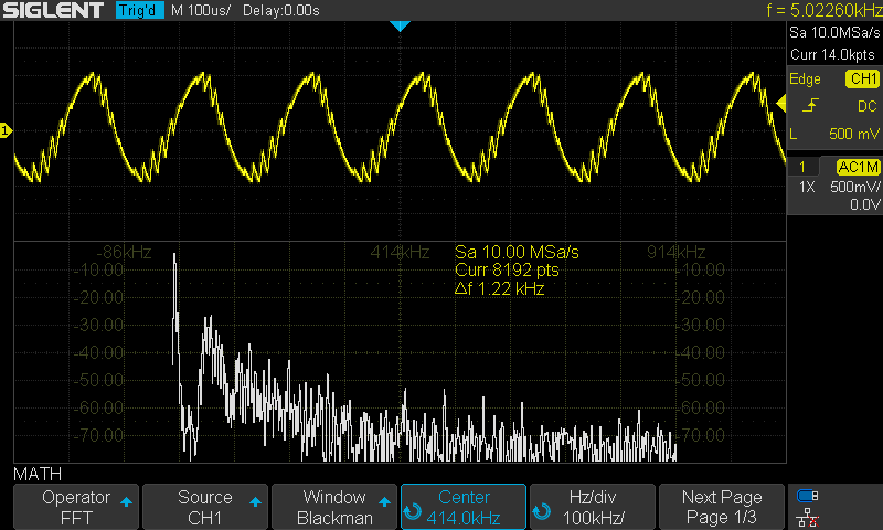
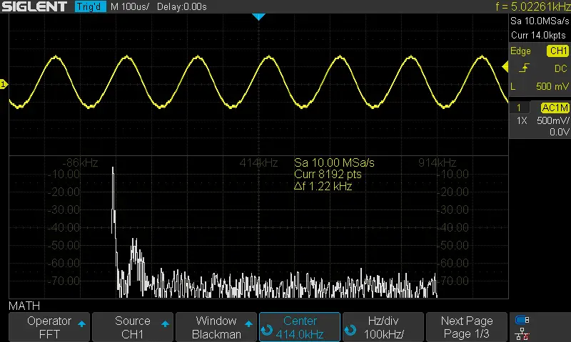
Here is the result for the 4th test (sine wave @ 5KHz)
The FFT shows a THD of nearly 15% or worse which is terrible. We can improve this by cascading the RC filter to increase the order and force more attenuation to the FPWM harmonics and improve the THD and that’s what actually happened after cascading the filter. Here are the results for both the tests before and after increasing the filter’s order.
Did you find this helpful? If yes, please consider supporting this work and sharing these tutorials!
Stay tuned for the upcoming tutorials and don’t forget to SHARE these tutorials. And consider SUPPORTING this work to keep publishing free content just like this!
| Previous Tutorial | Tutorial 30 | Next Tutorial | |||||
Hi Khaled, you are doing great job.
Can drop the source code of the project.
If you wish please explain the following configuration in STM32 Timer because I mostly use CubeMX to generate the STM32 projects and I don’t know the lots of configuration in it.
1. sConfigOC.OCMode = TIM_OCMODE_PWM1;
1-> Difference between TIM_OCMODE_PWM1 & TIM_OCMODE_PWM2
2. sConfigOC.OCFastMode = TIM_OCFAST_DISABLE;
2-> What is the meaning of this configuration this has great impact on my project if I enabled it.
I know the dead time but can’t understand the following configuration in dead time
3. sBreakDeadTimeConfig.OffStateRunMode = TIM_OSSR_DISABLE;
4. sBreakDeadTimeConfig.OffStateIDLEMode = TIM_OSSI_DISABLE;
5. sBreakDeadTimeConfig.LockLevel = TIM_LOCKLEVEL_OFF;
6. sBreakDeadTimeConfig.BreakState = TIM_BREAK_DISABLE;
7. sBreakDeadTimeConfig.BreakPolarity = TIM_BREAKPOLARITY_HIGH;
8. sBreakDeadTimeConfig.AutomaticOutput = TIM_AUTOMATICOUTPUT_DISABLE;
Thank you…