In this tutorial, we will delve into the working principles of phase shift oscillators, their types, applications, and how to design them. we’ll discuss how to implement two versions of the RC phase shift oscillator circuit using Op-Amp and BJT. How to set the oscillation frequency to your desired value. And finally, test everything out.
Table of Contents
- What is a Phase Shift Oscillator?
- Types of Phase-Shift Oscillators
- RC Phase-Shift Oscillator Principles of Operation
- RC Phase-Shift Oscillator Circuit Diagram
- RC Phase-Shift Oscillator Formula
- RC Phase-Shift Oscillator Circuit Example
- Applications of RC Phase Shift Oscillators
- Advantages & Disadvantages of RC Phase Shift Oscillators
- Concluding Remarks
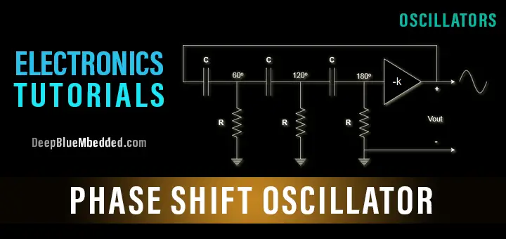
What is a Phase Shift Oscillator?
Phase shift oscillators are electronic circuits that generate a continuous, sinusoidal signal of a specific frequency. They are commonly used in electronic applications such as audio signal generation, frequency modulation, and tone generation.
An RC Phase Shift Oscillator produces a sinusoidal output signal by utilizing the phase shift principle. The circuit consists of an amplifier with a feedback loop containing a network of resistors and capacitors. The phase shift network provides a 180-degree phase shift at the oscillator’s frequency. The amplifier’s gain provides the remaining 180-degree phase shift required for oscillation.
Types of Phase-Shift Oscillators
There are two main types of phase shift oscillators: RC phase shift oscillators and LC phase shift oscillators.
RC Phase Shift Oscillator
An RC phase shift oscillator is a simple, low-cost circuit that utilizes a chain of three RC sections to produce the desired phase shift. The output of the amplifier is fed back through the RC network, which creates a phase shift of 60 degrees per section. Three sections in series provide a total of 180-degree phase shift, which is the minimum required for oscillation.
LC Phase Shift Oscillator
An LC phase shift oscillator uses a series of inductors and capacitors to provide the required phase shift. It is more stable and accurate than an RC phase shift oscillator but is more complicated and costly. The LC oscillator’s feedback network consists of three LC sections, with each section providing a phase shift of 60 degrees.
RC Phase-Shift Oscillator Principles of Operation
The basic structure of the RC phase shift oscillator consists of 3rd-order cascaded RC filters and a negative-gain amplifier (-K). The oscillation occurs at the frequency where the total phase shift through the 3 RC circuits is 180°. The negative gain of the amplifier stage (-K) will add another 180° phase shift. Resulting in a total phase-shift of 360° or 0° which is the required condition for oscillation.
For sustained oscillation, there is a required condition that must be met. It’s called “Greater Than 1 Total Loop-Gain“. The attenuation B of the 3rd-order RC feedback loop network is

Therefore, to meet the >1 total loop gain condition, the closed-loop gain of the amplifier K must be set to be slightly higher than 29. This will guarantee a sustained oscillation at the frequency Fr which can be calculated using the below formula.
RC Phase-Shift Oscillator Circuit Diagram
The general form for the RC phase shift oscillator is shown in the diagram below.
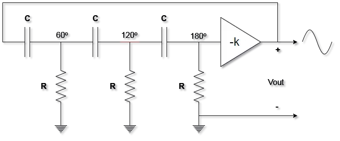
As you may have noticed, the circuit consists of 2 main parts
I- 3rd-Order Cascaded RC Filters
And you can pick the value for R and C to set your desired output frequency as we’ll discuss later.
II- Negative-Gain Amplifier
It can be realized using an op-amp or a BJT transistor. The value of the gain K should be carefully set for sustained oscillation. This will also be discussed in the next section.
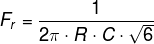
RC Phase-Shift Oscillator Formula
Fundamental Heuristic
To maintain a sustained oscillation, the condition below must always be met

Design Equations
To set the desired output frequency, use the following formula
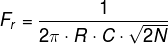
Please be advised that the above equations are not general for all RC phase shift oscillators. They only hold true for 3rd-order RC network-based oscillators. But for higher orders, the frequency at which oscillation occurs will change and you can use the below formula, where N is the order of the RC network.
RC Phase-Shift Oscillator Circuit Example
There are a couple of ways to implement the RC phase shift oscillator. Each of which deploys a different element for creating the “Negative-Gain Amplifier”. The first one uses an Op-Amp, and the other one uses a BJT transistor as an amplifier.
Let’s assume we’re using resistors of R = 5000Ω, and capacitors of C = 1nF, then the output frequency Fr should be as follows
1. RC Phase Shift Oscillator Using OpAmp
Design
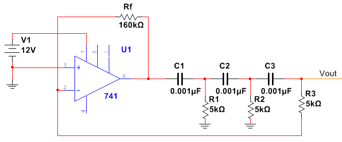
The ration Rf/R3 determines the closed-loop gain that should be >29. Which means we can pick Rf > R3*29
Rf > 145KΩ .. I’ve chosen 160KΩ
Simulation
Let’s Hook an oscilloscope’s probe to the output rail and see how it looks like in simulation!
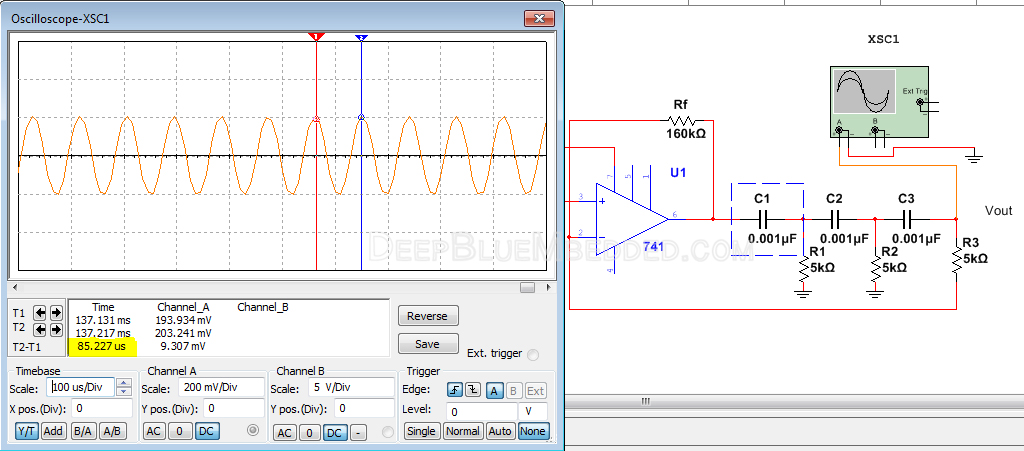
The resulting output frequency Fr is, therefore,
Obviously, it’s not perfect but it’s close enough to the theoretically calculated value of 13KHz.
Here is an animation showing how the signal builds-up to the point where it becomes sustainably oscillating.
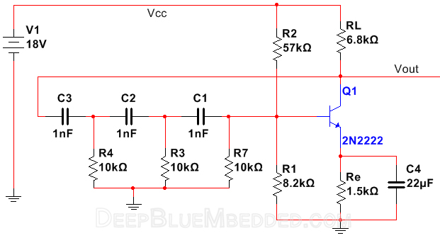
2. RC Phase Shift Oscillator Using BJT Transistor
Design
Another way to implement the RC phase shift oscillator is to use a BJT transistor as an amplifier instead of the Op-Amp showed above.
Let’s assume that it’s desired to get a sinusoidal output waveform oscillating @ a frequency Fr = 6.5KHz. We’ve got some capacitors of C = 1nF, therefore, we’ve got to calculate the value of the resistance R in order to get our circuit to oscillate @ 6.5KHz. We’ll also use the same equation for the output frequency
Substituting by the given values
By solving for R, we’ll find that

Now, we’ve got everything we need in order to implement & build our new design. The schematic diagram for the circuit will look like the figure below.
Simulation
Let’s Now hook an oscilloscope’s probe to the output rail and see how it looks like in simulation!
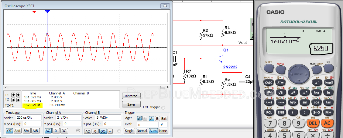
As you can see, the resulting output frequency Fr = 6.25KHz which is very close to the theoretically calculated desirable frequency of 6.5KHz. That’s cool, you can now vary R resistors and C capacitors to set the output frequency to whatever value you need.
Here is an animation showing how the signal builds-up to the point where it becomes sustainably oscillating.
Applications of RC Phase Shift Oscillators
Phase shift oscillators are commonly used in electronic applications, such as:
- Audio signal generation
- Tone generation
- Frequency modulation
- Local oscillator circuits in radio and TV receivers
- Inverter circuits for power electronics
Advantages & Disadvantages of RC Phase Shift Oscillators
Phase shift oscillators have several advantages and disadvantages which can be listed as follows:
Advantages
- Simple and low-cost circuit design
- Can generate frequencies from a few Hz to several MHz
- No external components are required for frequency stability
Disadvantages
- Sensitive to changes in temperature, humidity, and component tolerances
- Less stable than other types of oscillators
- Limited frequency stability and tuning range
Concluding Remarks
Phase shift oscillators are versatile and widely used in electronic applications. They generate a continuous, sinusoidal signal of a specific frequency and can be designed using simple RC or more complicated LC circuits. They have several advantages and disadvantages that should be considered when designing an oscillator circuit.
Phase shift oscillators utilize a feedback network that provides a 180-degree phase shift to the amplifier’s output signal. The amplifier’s gain provides the remaining 180-degree phase shift required for oscillation.
The two main types of phase shift oscillators are RC and LC phase shift oscillators.
To design a phase shift oscillator, you need to determine the frequency of the output signal and the type of oscillator circuit you want to use. The frequency of oscillation is determined by the values of the resistors and capacitors in the feedback network, which can be calculated using the formula mentioned earlier in the article.
Phase shift oscillators are commonly used in applications such as audio signal generation, tone generation, frequency modulation, local oscillator circuits in radio and TV receivers, and inverter circuits for power electronics.
The advantages of phase shift oscillators include a simple and low-cost circuit design, the ability to generate frequencies from a few Hz to several MHz, and no external components required for frequency stability.
However, phase shift oscillators are sensitive to changes in temperature, humidity, and component tolerances, less stable than other types of oscillators, and have limited frequency stability and tuning range.
Perfect Explanation!
Thanks for your kind feedback