| Previous Tutorial | Tutorial 13 | Next Tutorial | |||||
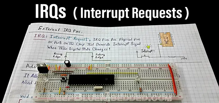
| IRQ | Interrupt Request Pins | |||||||
| Introductory Level ★☆☆☆☆ | |||||||
In this tutorial, you’ll get to know what are IRQ pins? Why we need them? How to use these pins. We’ll also develop the necessary firmware in order to create IRQ handlers for our PIC Microcontroller chip. This is going to be an extremely easy tutorial. So let’s get started!
[toc]
Components Needed For This Tutorial
| Quantity | Component Name |
| 1 | PIC16F877A |
| 1 | Breadboard |
| 1 | Jumper Wires Pack |
| 2 | 330Ω Resistors |
| 2 | 10KΩ Resistors |
| 2 | Push Button |
| 2 | LED (Green + Yellow) |
| 1 | 4MHz Crystal OSCillator |
| 1 | LM7805 Voltage Regulator |
| 1 | 9v Battery or any Power Supply Source |
| 1 | PICkit3 (PIC Programmer) |
What Is An IRQ?
IRQ stands for interrupt requests. There are actually some dedicated hardware physical pins that are capable of receiving external interrupt requests. The number of the available IRQ pins varies from a microcontroller chip to another. It’s quite uncommon to find a microcontroller chip with no IRQ pins at all.
An IRQ pin can fire an interrupt signal to the CPU in order to suspend the main routine being executed. The interrupt firing occurs on several events on an IRQ pin. It could be one of the following events
- Low (Level-Triggered)
- High (Level-Triggered)
- Rising Edge (Edge-Triggered)
- Falling Edge (Edge-Triggered)
- IOC (interrupt-On-Change)
And we (as programmers) are in charge of determining on which event an interrupt signal should be fired! Then we write an ISR to handle (service) it.
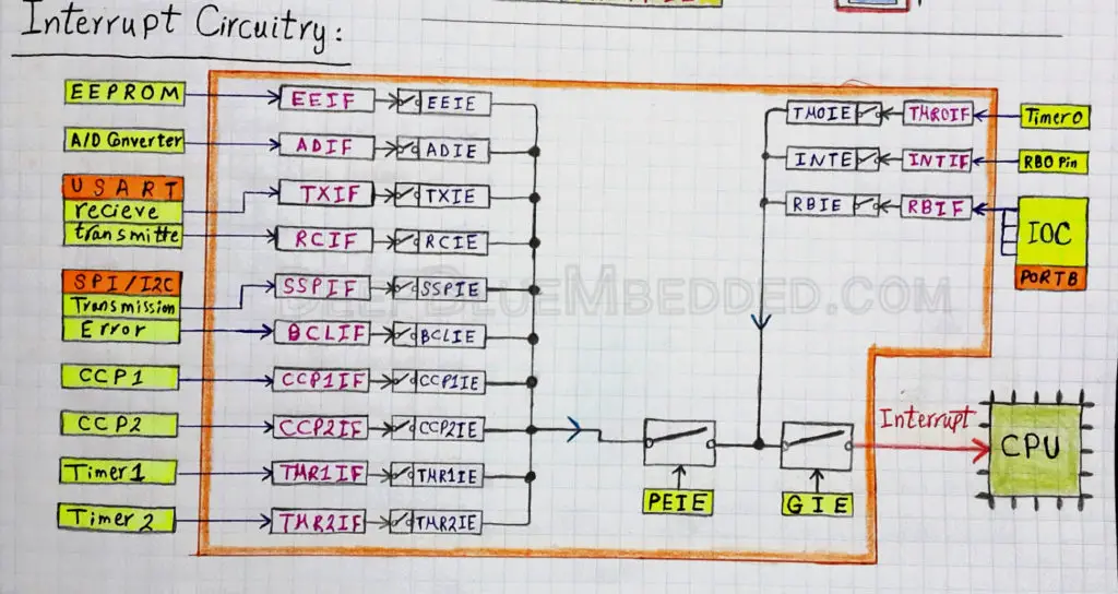
In the Microchip PIC16F877A Microcontroller that we’re using for these tutorials, there are basically two types for IRQ pins.
- RB0 INT (edge-triggered)
- PORTB IOC (interrupt-on-change)
The RB0 pin has a dedicated hardware interrupt request with a specific interrupt flag bit. That’s what makes this IRQ pin very special one as it has no shared hardware with any other interrupts.
On the other hand, the PORTB IOC are the 4-pins (RB4 to RB7). They are actually sharing a common flag bit which means any change in the state for any of these pins will generate an IOC interrupt signal. This means that we must keep track of the state of each IOC pin in order to spot the pin whose state has actually changed. The IOC interrupt flag bit won’t provide a clear information about which pin has fired the interrupt signal. As any of the 4-IOC pins can and will fire an IOC interrupt upon a state change.
Why We Need IRQ Pins?
Polling GPIO pins is a common practice in embedded systems. However, in some critical cases, we can’t do so. If we’re in a situation where an instantaneous response is substantially critical, then polling the io pins will make no sense!
As we’ve discussed earlier in this series of tutorials, that polling io pins is something like sitting by the phone and calling the client each minute (from time to time) to make sure he doesn’t need servicing. Why should you do this in the first place? if he can just call for help (servicing) when he needs it!
That’s why we need IRQ pins in our MCU chip in order to handle such a kind of urgent events on io pins. In this tutorial, we’ll be configuring the IRQ pin available on our PIC Microcontroller and do some testing to make sure everything is running as it should be.
How To Develop An IRQ Handler?
The process of developing an IRQ handler can be reduced to 3 basic steps as follows.
Step1 – Select The IO pin and Edge
First of all, we’ve to select the IRQ pin that we’ll be working with. In our PIC16F877A, there is only one dedicated pin for external interrupt requests RB0. And there are some GPIO pins from PORTB sharing an IOC (interrupt on change) request. For this tutorial, we’ll be using the RB0 INT.
The RB0 INT can, and will, fire an interrupt signal upon receiving one of this couple of events: Rising edge & falling edge. Choosing the edge at which an interrupt occurs is done be setting or clearing the INTEDG bit of the OPTION_REG register. We’ll set it so as to get an interrupt signal on every rising edge on the RB0 pin.
|
1 |
INTEDG = 1; // Interrupt Occurs On Every Rising Edge |
Step2 – Configure The RB0 Interrupt
Using the interrupt logic diagram (in datasheet 14.11) as we’ve discussed earlier in the tutorial of interrupts. The RB0 INT will be configured as follows
|
1 2 |
INTE = 1; // IRQ (RB0 INT) Interrupt Enable GIE = 1; // Global Interrupt Enable |
Step3 – Write The ISR Handler
We’ve done this step many times up till now. So it should be an easy task to write an ISR handler for any given interrupt source. This is done in c-code as follows
|
1 2 3 4 5 6 7 8 |
void interrupt ISR() { if (INTF == 1) // Check The Flag { // Do Some Stuff... INTF = 0; // Clear The Flag } } |
IRQ Interrupts – LAB
| Lab Name | IRQ |
| Lab Number | 10 |
| Lab Level | Beginner |
| Lab Objectives | Learn how to use IRQ Pin Interrupt request. And spot the major difference between normal GPIO pins and the IRQ pins. |
1. Coding
Open the MPLAB IDE and create a new project name it “IRQ”. If you have some issues doing so, you can always refer to the previous tutorial using the link below.

Set the configuration bits to match the generic setting which we’ve stated earlier. And if you also find troubles creating this file, you can always refer to the previous tutorial using the link below.

Now, open the main.c file and let’s start developing the firmware for our project.
Our task is to create a laggy routine of an LED that’s blinking once/2sec with __delay_ms() macro. And Configure another LED output pin in order to toggle upon each rising edge on the RB0 IRQ pin.
|
1 2 3 4 5 6 7 8 9 10 11 12 13 14 15 16 17 18 19 20 21 |
void main(void) { //--[ Configure The IO pins ]-- TRISC1 = 0; TRISC2 = 0; //--[ Configure The RB0 IRQ Interrupt ]-- INTEDG = 0; INTE = 1; GIE = 1; // Create The Main loop while(1) { // Green LED Blinking Routine RC2 = 1; __delay_ms(1000); RC2 = 0; __delay_ms(1000); } } |
Now, it’s the time to create the ISR handler for the RB0 (interrupt request).
|
1 2 3 4 5 6 7 8 9 |
void interrupt ISR() { if (INTF == 1) // Check The Flag { // Toggle The Yellow LED RC1 = ~RC1; INTF = 0; // Clear The Flag } } |
The firmware is now done. Let’s go simulate this simple project!
2. Simulation
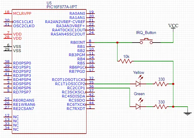
Here is the schematic diagram that you should be creating right now in your simulation environment software. Add the hex file and start testing everything out.
3. Prototyping
Hooking a couple of LEDs and a push button shouldn’t be that kind of a big deal. Plug-in the power pins and test everything out. It should work flawlessly! And here is a video for the running project in case you’re curious or if it’s not interesting enough for you to do it practically.
 |
IRQ Pins VS GPIO Pins
You might be remembering the tutorial of interrupt where we were comparing the interrupt-driven systems VS the io polling method. Usually, many of the newcomers to the embedded firmware programming do not realize the full potential of IRQ pins. That’s why they may be wondering about leaving the normal gpio pins and taking the hassle of setting up an IRQ pin interrupt.
The previous LAB was intended to show you that even with a laggy system with 2-significant delays, we can still get an instantaneous response to an external event on an io pin! Thanks to the IRQ pins available on the chip. We’ll now be adding a normal gpio pin to make the exact same function as RB0 IRQ and we’ll compare the response of each of them.
|
1 2 3 4 5 6 7 8 9 10 11 12 13 14 15 16 17 18 19 20 21 22 23 24 25 26 27 28 29 30 31 32 33 34 35 36 37 38 39 40 41 42 43 44 45 46 47 48 |
#include <xc.h> #include "config.h" #define _XTAL_FREQ 4000000 void main(void) { //--[ Configure The IO pins ]-- TRISC1 = 0; TRISC2 = 0; // Set The LEDs To Be Initially Off RC1 = 0; RC2 = 0; // Set The GPIO Pin RB1 To Be Input Pin TRISB1 = 1; //--[ Configure The RB0 IRQ Interrupt ]-- INTEDG = 0; INTE = 1; GIE = 1; // Create The Main loop while(1) { // Green LED Blinking Routine RC2 = 1; __delay_ms(1000); RC2 = 0; __delay_ms(1000); // Check For The RB1 Button (Polling) if (RB1) { // Toggle The Yellow LED RC1 = ~ RC1; } } return; } //--[ The ISR Handler ]-- void interrupt ISR() { if(INTF) { // Toggle The Yellow LED RC1 = ~ RC1; INTF = 0; } } |
And here is the simulation results for each of the 2-cases we’ve discussed.
|
Concluding Remarks
1
Normal GPIO pins can never replace IRQ interrupt pins. That’s why you should carefully choose the microcontroller platform for your project in order to have sufficient hardware IRQ pins available.
2
Loading a timer module with its maximum capacity value-1 and operating it in counter mode can give you a theoretical equivalent to an extra IRQ pin. Moreover, playing with CCP modules can also give you an extra IRQ pin theoretically. However, these modules are not designed to be used in this way and you shouldn’t put yourself in such a situation in the first place. But if it’s the case, you can work around and make yourself some extra IRQ pins.
| Previous Tutorial | Tutorial 13 | Next Tutorial | |||||
Another great tutorial. I have something to ask. İf there is two interrupt routines; for example if there is timer1 interrupt and this IRQ interrupt and let’s say both happens at the same. Is there a priority to interrupts?
Low-end MCUs do not have such a thing. If two interrupts happened in the same time, the first one is serviced first.
However in most of the nowadays MCUs do have a programmable prioritization for interrupts that let’s you decide on which interrupt is of a higher priority and so.