| Previous Tutorial | Tutorial 6 | Next Tutorial | |||||
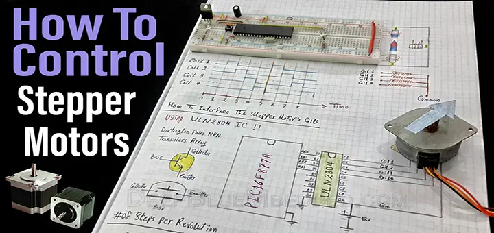
| How To Control Stepper Motors With PIC MCUs | |||||||
| PIC Microcontrollers Course Home Page ???? | |||||||
In this tutorial, you’ll learn how stepper motors work and how to control/drive a stepper motor with PIC microcontrollers in MPLAB with XC8. How to control the direction and speed of a stepper motor with PIC microcontrollers. We’ll discuss the theoretical principles of operation then we’ll develop the required firmware and circuitry to implement and test everything in practice. Using unipolar stepper motors with ULN2003 driver IC or equivalents.
[toc]
Components Needed for this tutorial
| Qty. | Component Name | Buy On Amazon.com |
| 1 | PIC16F877A | Add |
| 1 | BreadBoard | Add |
| 1 | Stepper Driver (ULN2003 or A988) | Add |
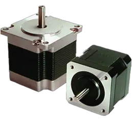
| 1 | Stepper Motor (Unipolar or Bipolar) | Add Add |
| 2 | Push Buttons | Add |
| 1 | Resistors Kit | Add Add |
| 1 | Capacitors Kit | Add Add |
| 1 | Jumper Wires Pack | Add Add |
| 1 | LM7805 Voltage Regulator (5v) | Add |
| 1 | Crystal Oscillator | Add |
| 1 | PICkit2 or 3 Programmer | Add |
| 1 | 9v Battery or DC Power Supply | Add Add Add |
What Are Stepper Motors?
This is a rotary actuator that is being used for a variety of applications which require high precision high torque kind of motor. It fits really well with sophisticated devices where accuracy is mandatory (e.g. CNC Machines, 3D Printers, etc.), while the DC motors are being used in applications where the speed of rotation is crucial.
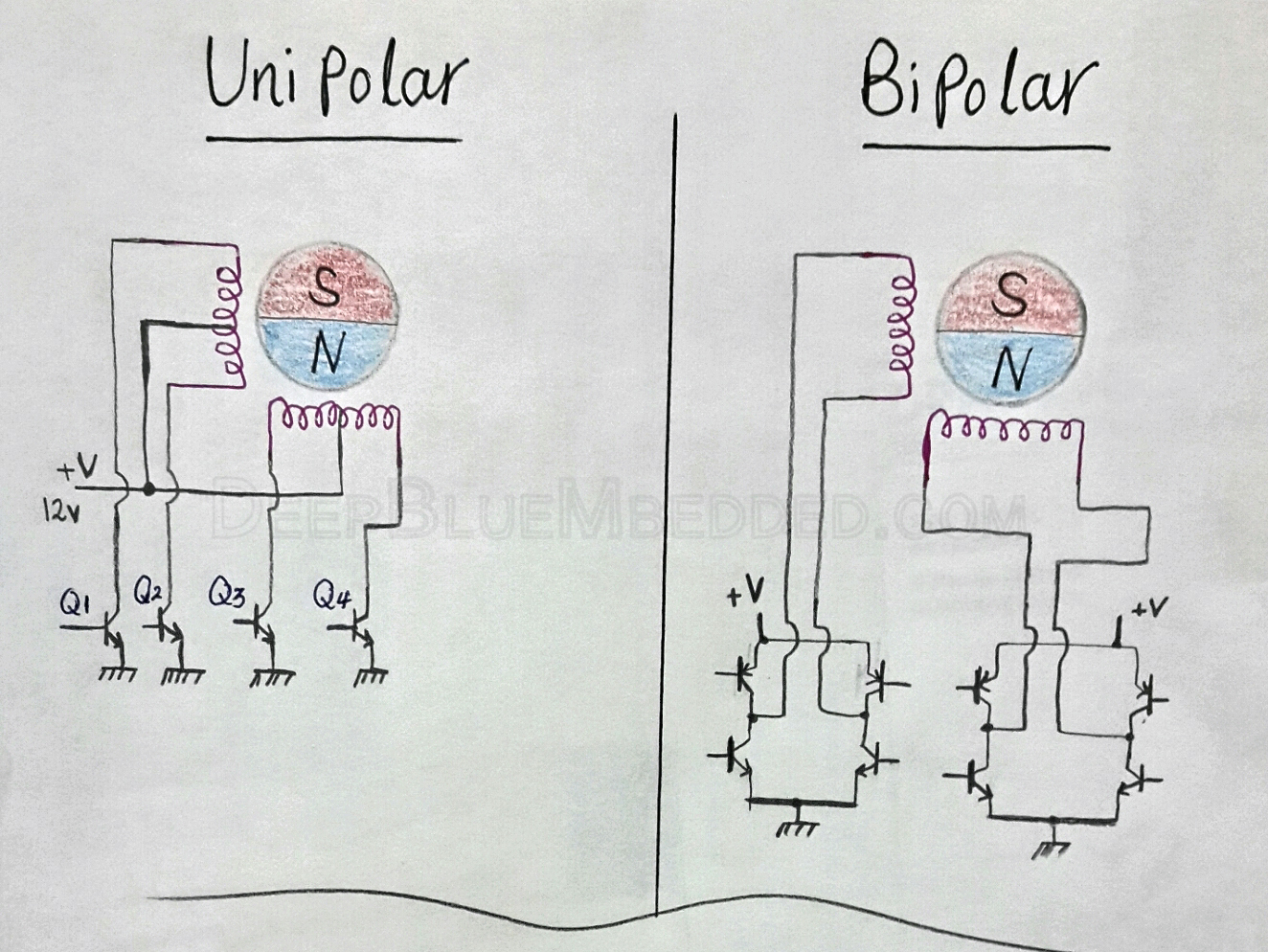
Stepper motors come into two different major types: unipolar & bipolar winding arrangements. The actuator we’ll be using in this tutorial is a Unipolar Stepper Motor.
Stepper motors could be also identified by some extra few factors other than the winding arrangement. The rated supply voltage for many stepper motors ranges between (5-24) v. The rated current is also another factor that is always in proportion with torque. I always bet that the stepper motor’s torque is the number-1 factor to consider while buying a new stepper motor for whatever project.
Stepper Motor Resolution
In many situations, the number-1 factor to consider about a stepper motor is its Resolution! The resolution of a stepper motor is the number of degrees it rotates per step (degrees/step). The most used stepper motors have 7.5°/step and 1.8°/step. The unipolar motor which we’ll be using has a resolution of 7.5°/step.
How do Stepper Motors work?
Generic Stepper Motor
The basic concept of operation for stepper motors is almost the same, whether it’s bipolar or unipolar. We’ve got a magnet as a rotor core in the middle. On the sides, it’s the stator’s winding (coils) which generate the magnetic field required to force the magnetic core to rotate. We can think of a generic stepper motor as if it looks something like the figure below (just an approximation for demonstration purposes only).
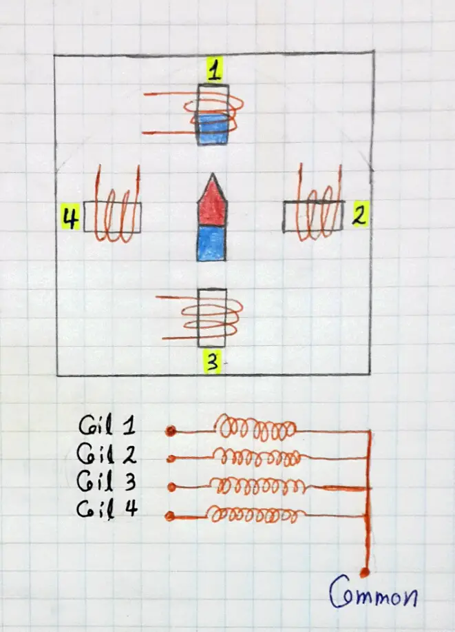
This is a simplified version of the real winding that resides within actual stepper motor, but theoretically, it’s almost the same. The magnetic core gets attracted to whatever coil if it gets energized. Well, if you’re about to command this motor to rotate in a clockwise direction, you should activate (energize) the coils one at a time in the following order (1, 2, 3, 4, 1, and so on). The magnetic core will follow the stator rotating field in the same direction.
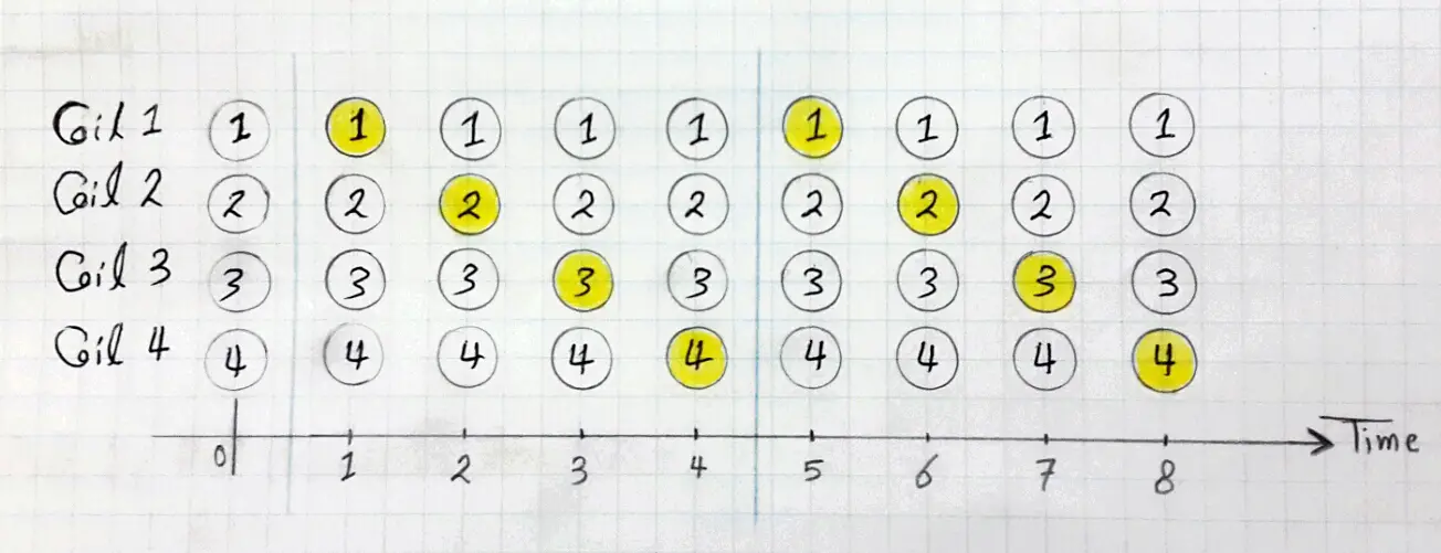
At the first time instance, only coil-1 is activated and the rest are OFF. In the 2nd instance, only coil-2 is ON and the rest are OFF, and so on. This will obviously result in a clockwise rotation for the stepper motor.
Full-Step VS Half-Step
The transition from a coil to another is called Full-Step. That’s one phase at a time. In fact, there is a much smaller stepping mode for operating the same motor. It’s called Half-Step. For example, if we’ve activated coil-1 and coil-2 at the same time, the core will obviously stay in between. It won’t point toward coil-1 either coil-2, but somewhere in between, This is called a half-step. For this tutorial, we’ll be following the full-stepping scheme as it’s a little bit simpler to implement.
Now, let’s discuss the differences between the unipolar & bipolar winding in more detail.
Unipolar
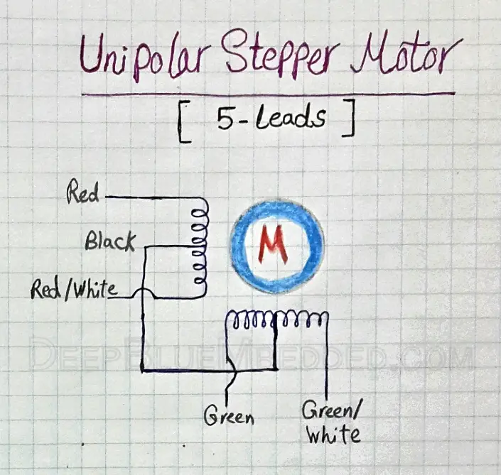
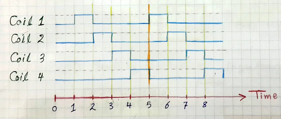
A Unipolar stepper motor typically has one winding with a center tap per phase. Each half of the winding is activated (energized) in each direction of the magnetic field. Activating each winding is a relatively simple process as the arrangement itself has a magnetic pole which can be reversed without polarity inversion (switching the direction of the current flow). The rest of the work is left to the µC which will activate these coils in a specific order to achieve CW or CCW rotation. A typical timing diagram for a stepper motor coil activation sequence will look like the one shown below.
Bipolar
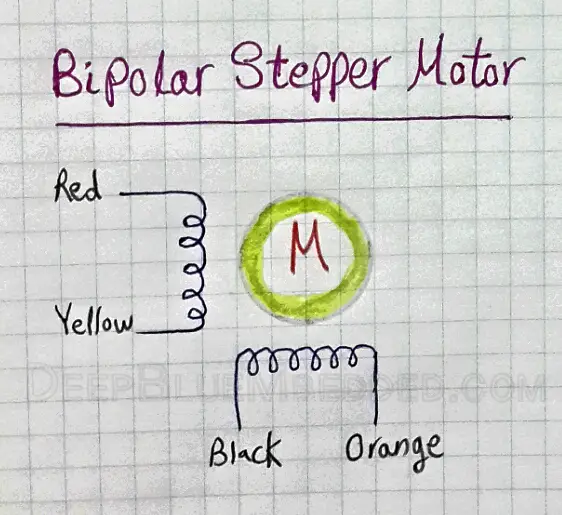
A Bipolar stepper motor typically has only one winding per stator phase. A two-phase bipolar stepper motor will obviously have 4 leads. There is no common lead for bipolar stepper motors, unlike the unipolar ones. That’s why there isn’t inherent polarity inversion. Which means we’ve to add H-Bridge driver circuitry in order to achieve the required polarity inversion.
Unipolar VS Bipolar
Both unipolar & bipolar stepper motors are being used in a very wide range of applications across the makers’ community. However, each of these arrangements has its own advantages and drawbacks.
The unipolar stepper motors, for instance, could be easily controlled with a µC & an array of transistors IC (e.g. ULN2003). But, you’ll easily notice their low-torque. This is obviously due to the fact that the current passes through only half of the winding (coil) at a time.
The bipolar stepper motors, on the other hand, are much harder to control and interface. You have to construct a polarity reversing driver circuitry (e.g. H-Bridge) which is a bit more complex to build. But the positive side is that you’ll end up having a higher torque due to the current flow through the entire winding (coil).
How To Interface Stepper Motors With PIC uC?
Motors, actuators, and other loads cannot be directly hooked to whatever microcontroller at any cost. This will obviously result in an over-current damage to your µC. If you still remember from tutorial4, that the maximum current that could be sourced or sunk by any IO pins is capped at 25mA.
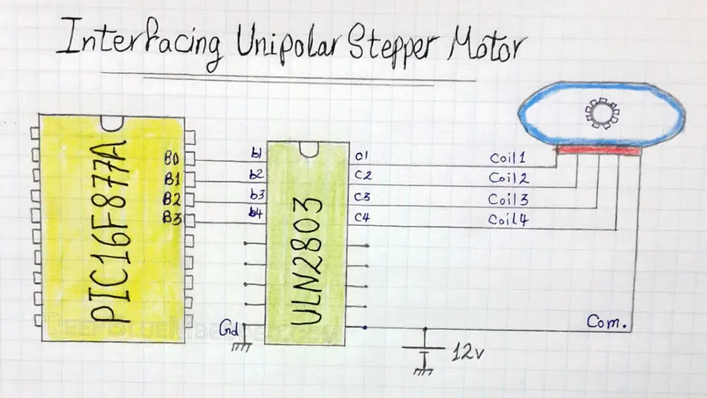
For this reason, we’ll be using an array of 4-transistors in order to interface (switch) the stepper motor’s winding (coils) ON & OFF. The integrated solution for this purpose is the IC called ULN2803 which is basically Darlington pairs of 8-Transistors.
This chip will operate as an interface between the microcontroller’s 4-output pins & the stepper motors winding 4-coils. It should also be connected to the power source required for driving the motor. You should check your motor’s datasheet to be sure of the operating voltage whether it’s 5v, 12v, or whatever.
You can download the datasheet for the stepper motor which I’m using for this tutorial through this link.
Download Unipolar Stepper Motor Datasheet
The connection diagram for this chip is shown down below.
| Check Out This New Tutorial For Stepper Motor Control With STM32. And How To Build A Library That Controls The Speed, Direction, And Drive Mode For Different Stepper Motor Configurations. |  |
|
PIC Microcontroller Driving a Stepper Motor – LAB
| Lab Name | Driving Stepper Motor |
| Lab Number | 4 |
| Lab Level | Beginner |
| Lab Objectives | Learn how to drive stepper motors, write the necessary firmware to make it rotate 1 complete CW (clockwise) rotation then another 1 rotation CCW (counter-clockwise), and build the necessary hardware circuitry in order to drive our motor properly. |
1. Coding
Open the MPLAB IDE and create a new project name it “Stepper_Driver”. If you have some issues doing so, you can always refer to the previous tutorial using the link below.

Set the configuration bits to match the generic setting which we’ve stated earlier. And if you also find troubles creating this file, you can always refer to the previous tutorial using the link below.

Now, open the main.c file and let’s start developing the firmware for our project.
Our task is to output the bit-pattern shown previously in order to make the stepper motor rotate a complete rotation in CW direction, then reverse the output bit-pattern in order to achieve a CCW rotation, and keep repeating this behavior.
The unipolar stepper motor we’re using has a resolution of 7.5°/step. Which means a complete rotation will obviously require 360/7.5 = 48 Full-Step!
Let’s say we’ll be using PORTB as the output port. As we’ll hook the least significant 4-pins (B0, B1, B2 & B3) to the 4-coils’ driver transistors within the ULN2803 IC chip. To set these pins [RB0 to RB3] to be output pins and initialize these pins’ states to be LOW (logic 0), we’ll write the following code.
|
1 2 3 4 5 6 7 8 9 |
TRISB0 = 0; TRISB1 = 0; TRISB2 = 0; TRISB3 = 0; RB0 = 0; RB1 = 0; RB2 = 0; RB3 = 0; |
Well, this could be done in a much simpler way. As long as we aren’t using pins [RB4 to RB7], by setting the whole PORTB to be output port and initializing all it’s pins to be LOW. Only 2 LOC will do the hack.
|
1 2 3 4 5 6 7 8 9 10 11 12 |
void main () { TRISB = 0x00; PORTB = 0x00; // Initialized to be LOW while (1) { // Rotate CW ... // Rotate CCW ... } } |
| Note | |||
|
It’s a preferred practice to give initial values (states) to your output pins right after setting them to be output pins. This ensures a glitch-free output line which is substantial for sensitive systems in particular. |
|||
And now, we’re done with the configurations part. Let’s move next to the system’s main Loop. In which we’ll rotate CW & CCW.
CW Rotation
The order of sequentially activated coils determines the motor’s direction of rotation. If activating the coils in this order [1 -> 2 -> 3 -> 4] results in a CW rotation, then activating them in this order [4 -> 3 -> 2 -> 1] results in a CCW rotation. Each consecutive 2-Steps are separated with a time delay called StepDelay. The following code will show you how we can implement these concepts in C.
|
1 2 3 4 5 6 7 8 9 10 11 12 |
// Create Bit-Shifting Variable unsigned char i=0; // Turn One Side for (int j=0; j<48; j++) { PORTB = (1<<i); i++; // Advance to the next output pin __delay_ms(100); // StepDelay if (i==4) i=0; } |
- The output bit-pattern @ PORTB during round-1 in this for loop will be (0000 0001). It’s the 8-Bit representation for the value (1) left-shifted by (i = 0) times.
- The output bit-pattern @ PORTB during round-2 in this for loop will be (0000 0010). It’s the 8-Bit representation for the value (1) left-shifted by (i = 1) times.
- The output bit-pattern @ PORTB during round-3 in this for loop will be (0000 0100). It’s the 8-Bit representation for the value (1) left-shifted by (i = 2) times.
- The output bit-pattern @ PORTB during round-4 in this for loop will be (0000 1000). It’s the 8-Bit representation for the value (1) left-shifted by (i = 3) times.
Which will result in the activation of each coil at a time exactly in the same order shown previously in this diagram.
After 48-round executing this for loop, the stepper will complete a Full-Rotation 360° in one direction.
CCW Rotation
In order to reverse the rotation direction, we’ll make a few changes to the previous code. As shown below
|
1 2 3 4 5 6 7 8 9 10 11 12 |
// Create Bit-Shifting Variable unsigned char i=0; // Turn The Other Side for (int j=0,i=0; j<48; j++) { PORTB = (8>>i); i++; __delay_ms(100); if (i==4) i=0; } |
| Note | |||
|
The decimal value that corresponds to this bit-pattern (1000) is 8 which will be right-shifted to get the following patterns (0100), (0010) and (0001). |
|||
Now, plug this code in your main.c file or download the full project code from the attachments section. Cross your fingers! Hit the compile button! And we’re done with the firmware.
2. Simulation
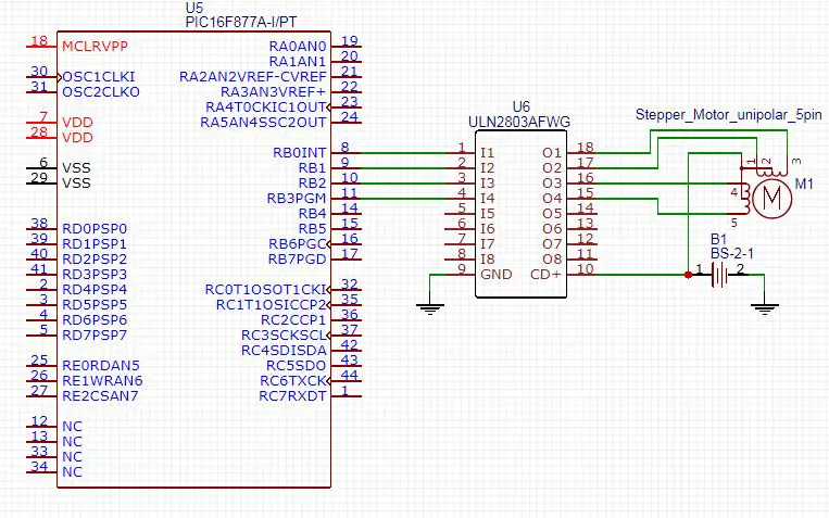
The schematic for this LAB is shown below. Just create a similar one in your simulator.
After connecting everything up in your simulator, you’ll have to double-click the MCU chip and point to the firmware code .hex file, make sure to simulate your project at the same oscillator frequency used in the code. Otherwise, the timing diagram will be messed-up.
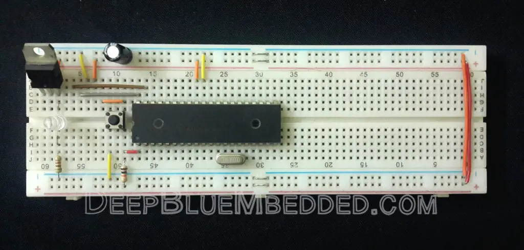
3. Prototyping
You should have created the basic prototyping setup which we’ve demonstrated previously. If you’ve any troubles doing so, you can refer to that previous tutorial.
The connections for the stepper motor and the ULN2803 IC will eventually be something like my board shown down below.
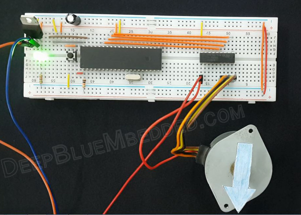
Connect your programmer’s ICSP port, Flash the Code, Plug the power supply and test this out!
The final running project in case you’re curious.
 |
Stepper Motor Controlled Motion With PIC uC – LAB
| Lab Name | Stepper Motor Controlled Motion |
| Lab Number | 5 |
| Lab Level | Beginner |
| Lab Objectives | Learn how to drive stepper motors, write the necessary firmware to make it rotate CW while an input button is pressed and CCW while another button is pressed, and build the necessary hardware circuitry in order to drive our motor properly. |
1. Coding
Open the MPLAB IDE and create a new project name it “Stepper_Controlled”. If you have some issues doing so, you can always refer to the previous tutorial using the link below.
Set the configuration bits to match the generic setting which we’ve stated earlier. And if you also find troubles creating this file, you can always refer to the previous tutorial using the link below.
Now, open the main.c file and let’s start developing the firmware for our project.
Our task is to output the bit-pattern shown previously in order to make the stepper motor rotate CW & CCW as a response to the user button press events. There will be 2 Push Button indeed, which will be hooked to a couple of input pins.
The output bit-patterns in both cases is typically the same as in LAB4. Hence the full c-code for this LAB will be as shown below.
|
1 2 3 4 5 6 7 8 9 10 11 12 13 14 15 16 17 18 19 20 21 22 23 24 25 26 27 28 29 30 31 32 33 34 35 |
void main(void) { // Create Bit-Shifting Variable unsigned char i=0; // Set PORTB 8-Pins To Be Output Pins TRISB = 0x00; // Set All PORTB Pins To Be OFF (Initially) ! PORTB = 0x00; // Set RC0, RC1 Pins To Be Input Pins TRISC0 = 1; TRISC1 = 1; // Create The System's Main Routine ! while(1) { // While Button1 is pressed, Rotate CW while(RC0) { PORTB = (1<<i); i++; __delay_ms(100); if (i==4) i=0; } // While Button2 is pressed, Rotate CCW while(RC1) { PORTB = (8>>i); i++; __delay_ms(100); if (i==4) i=0; } } return; } |
Cross your fingers! Hit the compile button! And we’re done with the firmware.
2. Simulation
The schematic for this LAB is shown below. Just create a similar one in your simulator.
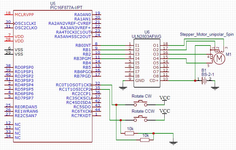
After connecting everything up in your simulator, you’ll have to double-click the MCU chip and point to the firmware code .hex file, make sure to simulate your project at the same oscillator frequency used in the code. Otherwise, the timing diagram will be messed-up.
3. Prototyping
You should have created the basic prototyping setup which we’ve demonstrated previously. If you’ve any troubles doing so, you can refer to that previous tutorial.
The connections for this LAB is no different from that of LAB4. However, make sure to connect the push button to RC0 & RC1 using (Pull-Down) resistors. Otherwise, the logic inversion will bring you into a real nightmare. Everything else should stay the same.
Connect your programmer’s ICSP port, Flash the Code, Plug the power supply and test this out!
The final running project in case you’re curious.
|
Stepper Motor Speed Control With PIC uC – LAB
| Lab Name | Stepper Motor Speed Control |
| Lab Number | 6 |
| Lab Level | Beginner |
| Lab Objectives | Learn how to drive stepper motors, write the necessary firmware to make it rotate at different speed levels, and build the necessary hardware circuitry in order to drive our motor properly. Finally, we’ll compare the results and draw in some conclusions. |
1. Coding
Open the MPLAB IDE and create a new project name it “Stepper_Speed_Control”. If you have some issues doing so, you can always refer to the previous tutorial using the link below.
Set the configuration bits to match the generic setting which we’ve stated earlier. And if you also find troubles creating this file, you can always refer to the previous tutorial using the link below.
Now, open the main.c file and let’s start developing the firmware for our project.
In this LAB, we’ll perform the exact same operation in LAB4. But we’ll control the speed of rotation by adjusting the StepDelay value. Which obviously controls for how long does it take the stepper motor to perform a Full-Step. Hence, we’ve got a full control over the time it takes the stepper motor to perform a complete rotation (48-Steps).
The full code listing for this LAB is as follows.
|
1 2 3 4 5 6 7 8 9 10 11 12 13 14 15 16 17 18 19 20 21 22 23 24 25 26 27 28 29 30 31 32 33 34 |
void main(void) { // Create Bit-Shifting Variable unsigned char i=0; // Set PORTB 8-Pins To Be Output Pins TRISB = 0x00; // Set All PORTB Pins To Be OFF (Initially) ! PORTB = 0x00; // Create The System's Main Routine ! while(1) { // Turn One Side for (int j=0; j<48; j++) { PORTB = (1<<i); i++; __delay_ms(x); // StepDelay if (i==4) i=0; } // Wait For a Second ! __delay_ms(1000); // Turn The Other Side for (int j=0,i=0; j<48; j++) { PORTB = (8>>i); i++; __delay_ms(x); // StepDelay if (i==4) i=0; } } return; } |
You should notice that __delay_ms is a macro, not a function. That’s why you can not pass a variable to it by any means. However, you can alternatively use the #define directive to define the x value to be whatever you want.
- We’ll start experimenting with x = 100. And observe the motor rotation speed.
- Then change it to x = 50. And observe the motor new speed.
- Now, let’s drop down the delay time to be too low. let x = 10. Observe what happens.
- Finally, let the StepDelay about 25ms, it should give you the maximum rotation speed without glitches.
Here is the final running project in each case. If you’re curious about it!
|
| Pro Tip | |||
|
The stepper motor’s rotation speed isn’t substantial in general situations. However, it could be easily controlled by adjusting the time-interval delays between each consecutive 2-steps. But you should be aware that there is a fundamental limitation of its speed. Everything you need to know concerning a specific stepper motor should be found in its datasheet. |
|||
| Note | |||
|
Controlling the speed of a stepper motor is kind of a trivial work. However, it could be very useful in some specific situations. But the thing to note here, is stepper motors are not used for applications that need high speed of rotation. For high-speed, you should look for a DC or a Brushless motor. But when it comes to precision & torque, you should look for a suitable stepper motor. That’s why it’s being used in 3D printers & CNC machines. |
|||
Simulation & prototyping steps for this LAB are typically the same as LAB4. So, I’m sure you’ll be able to conduct these experimentations on your own. Any files you may need are always included in the downloads section.
Get prepared for the next demo, it’s going to be a theoretical tutorial. However, it’s completely substantial for all of the futuristic practical LABs & Projects. So, stick around!
Downloadable Files
| PIC Microcontrollers Course Home Page ???? | |||||||
| Previous Tutorial | Tutorial 6 | Next Tutorial | |||||
How can i interface a unipolar stepper motor as a bipolar stepper motor
advice me with the suitable driver
Sir,
It’s very great. Learning and experimenting is made very simple in all of your lessons. I am greatly impressed in the presentation and by the way and learnt lot. I am really Thankful to you.
With High Regards.
Hello,
Great job this page !!
I am talking to you because I have plans to build this diagram, but I don’t know anything about online C code and compilation, and the site does not provide any .hex files!
This diagram is just used to run a motor with two buttons in one direction and in the other, plus a speed control!
The lines of codes are they complete, because I see that there is no value on the delay, (this can be done maybe by tests), the engine must be running continuously when the button is pressed, but do you think the rest of the program is good and free from errors?
http://ccspicc.blogspot.com/2016/05/pic16f877a-l293d-cd-rom-stepper-motor-control-circuit-ccs-pic-c.html
I hope you will be able to help me because there is not much diagram on the subject, and I have Pic 16F877A!
Thank you very much see you soon,
Pierre
You have chosen __delay_ms(100);
How little can the delay time be?