
| Previous Tutorial | Tutorial 11 | Next Tutorial | |||||
| ESP32 Timers & Timer Interrupts (Arduino) | |||||||
| ESP32 Course Home Page ???? | |||||||
In this tutorial, you’ll learn how to use ESP32 internal Timers & generate Timer Interrupt events in Arduino IDE. We’ll discuss how ESP32 Timers work, how to configure ESP32’s Timers, and how to generate periodic interrupts to synchronize the execution of logic within your project. And also measure the timer between two events whether they’re external or internal events.
We’ll be doing 2 different LABs in this tutorial. In the first LAB, we’ll be configuring one of the ESP32’s Timers to generate a periodic interrupt in which we’ll toggle an LED. In the 2nd LAB, we’ll measure the elapsed time between two external events using one of the ESP32’s Timers. Without further ado, let’s get right into it!
In this tutorial: 2 LABs
| LAB25 | ESP32 Timer Interrupt Generating Periodic Event |
| LAB26 | ESP32 Frequency Counter Project (Using Timer For Time Measurement) |
[toc]
Requirements For This Tutorial
Prior Knowledge
Software Tools
Hardware Components
You can either get the complete course kit for this series of tutorials using the link down below. Or just refer to the table for the exact components to be used in practical LABs for only this specific tutorial.
ESP32 Timers
The ESP32 SoCs come with 4 hardware timers, each of which is a general-purpose 64-bit up/down counter with a 16-bit prescaler. Except for ESP32-C3 which has only 2 timers each of which is 54 bits instead. The ESP32 timers have the capability of auto-reloading at the end of the counting period as well.
ESP32 Timers Functional Description
Each ESP32 timer uses the APB clock (APB_CLK which is normally 80 MHz in frequency) as a base clock. This clock is then scaled down
by a 16-bit prescaler which generates the time-base tick time. Therefore, we’ll be changing the value of the prescaler in order to control the timer tick time.
The 16-Bit prescaler can divide the APB_CLK by a factor from 2 to 65536. When you set the prescaler value to be either 1 or 2, the clock divisor is 2; when you set the prescaler to 0, the clock divisor is 65536. Any other value will cause the clock to be divided by exactly that value that you’ve written to the prescaler register.
ESP32 Timers Alarm Generation
ESP32 timers can trigger an alarm (Event) which will cause a timer to reload and/or interrupt to occur, depending on your configuration. The alarm event is triggered when the value you’ve stored in the alarm register matches the current timer value. This is very useful to set periodic interrupts to execute some pieces of logic periodically in your project as we’ll be doing hereafter.
ESP32 Timers Equation
In order to generate periodic events with ESP32, we’ll be using the alarm event generation as well as the timer’s prescaler in order to achieve the desired interrupt periodicity. There are 3 special cases for the Timer equation down below, which are when the prescaler value is = 0,1, and 2. When Prescaler=1or2, it’s going to be as follows [ TOUT = TimerTicks x (2/APB_CLK) ]. When Prescaler=0, it’s going to be as follows [ TOUT = TimerTicks x (65536/APB_CLK) ]. Otherwise, we can generally use the equation down below.
![]()
ESP32 Timer Example (Arduino)
Let’s say we’d like to toggle an LED every 1 ms without using a delay that blocks the CPU and does much harm to the overall timing performance of your system. For this, we’ll use the timer’s equation above, Given that the default APB_CLK is 80MHz or 80,000,000Hz. The desired TOUT for the interrupt period in which we’ll toggle the LED is 1ms, So TOUT = 1ms or 0.001s. The only two unknowns now are the Prescaler value and the TimerTicks count which we’ll set the alarm event to.
We can set the Prescaler to whichever value we want but for the sake of simplifying the calculations, let’s set the Prescaler=80. This will leave us with only one unknown which is the TimerTicks count. So, we’ll solve the equation for TimerTicks:
![]()
TimerTicks count will therefore = 1000. And this is how to implement it in Arduino code.
|
1 2 3 4 5 6 7 8 9 10 11 12 13 14 15 16 17 18 19 20 |
#define LED 21 hw_timer_t *Timer0_Cfg = NULL; void IRAM_ATTR Timer0_ISR() { digitalWrite(LED, !digitalRead(LED)); } void setup() { pinMode(LED, OUTPUT); Timer0_Cfg = timerBegin(0, 80, true); timerAttachInterrupt(Timer0_Cfg, &Timer0_ISR, true); timerAlarmWrite(Timer0_Cfg, 1000, true); timerAlarmEnable(Timer0_Cfg); } void loop() { // Do Nothing! } |
I’ve used Timer0 in this example, but you can use any one of the 4 available timers in ESP32. The LED toggle logic that we’d like to execute every 1ms is placed in the Timer0_ISR() function
The timerBegin() function configures the desired timer module with the desired timer prescaler value and counting direction up or down.
|
1 |
Timer0_Cfg = timerBegin(0, 80, true); |
This line of code above configures timer 0 to have a prescaler of 80 and count up (true=count_up, false=count_down). Those are the 3 arguments for this function call. the next line enables the Timer interrupt event and attaches its callback function to the desired ISR_Handler function that we’d like to execute periodically.
|
1 |
timerAttachInterrupt(Timer0_Cfg, &Timer0_ISR, true); |
Then, we write the desired TimerTicks count (1000) to the alarm register by the following line of code. Which also sets the auto-reload to be enabled (true=Enable auto-reload, false=Disable auto-reload).
|
1 |
timerAlarmWrite(Timer0_Cfg, 1000, true); |
Now, we only need to enable the timer in order to have it running continuously. This is done by the following line of code.
|
1 |
timerAlarmEnable(Timer0_Cfg); |
Consequently, the timer will have a prescaler of 80, and a clock of 80MHz. Which results in a TickTime=1μs. The alarm register is set to 1000, whenever the timer counts up to 1000 (after 1ms), this will trigger an alarm event & an interrupt signal. Therefore, the Timer0_ISR() function is called every 1ms. The auto-reload will reload the Timer register with a 0 and it starts counting up to 1000 again and so on.
ESP32 Timer Arduino APIs
Here is a list of the available ESP32 Timers APIs for Arduino Core users that you’ll most probably use in different projects.
ESP32 Timers General Arduino APIs
timerBegin
|
1 |
hw_timer_t * timerBegin(uint8_t timerNumber, uint16_t prescaler, bool countUpOrDown); |
This function is used to configure the desired timer module with the desired prescaler value and set the counting direction (up or down).
Note: this function doesn’t accept any prescaler value outside the range [2, 65535]. The datasheet mentions that you can still write 0, and 1 to get prescaler division factors of 65536 and 2 respectively. But, it gives an error while compiling in Arduino Core.
timerEnd
|
1 |
void timerEnd(hw_timer_t *timer); |
This function is used to de-init the timer instance that we’ve previously configured with timerBegin() function.
timerAttachInterrupt
|
1 |
void timerAttachInterrupt(hw_timer_t *timer, void (*fn)(void), bool interruptMode); |
This function is used to enable & attach an interrupt to the timer. It also sets the callback function to the ISR_Handler, and selects the interruptMode (true=Edge triggered or false=Level triggered). Only level trigger is supported as of the time of writing this tutorial.
timerDetachInterrupt
|
1 |
void timerDetachInterrupt(hw_timer_t *timer); |
This function is used to detach the interrupt from the timer.
timerStart
|
1 |
void timerStart(hw_timer_t *timer); |
This function is used to start the counter of the timer. It doesn’t automatically start after initialization with timerBegin() function call. You still need to call timerStart() in order to run the timer and start counting.
timerStop
|
1 |
void timerStop(hw_timer_t *timer); |
This function is used to stop the counter of the timer.
timerRestart
|
1 |
void timerRestart(hw_timer_t *timer); |
This function is used to restart the counter register of the timer.
timerWrite
|
1 |
void timerWrite(hw_timer_t *timer, uint64_t val); |
This function is used to set the counter register’s value of the specified timer module.
timerSetDivider
|
1 |
void timerSetDivider(hw_timer_t *timer, uint16_t divider); |
This function is used to change the prescaler (clock divider) value of the specified timer module. The initial prescaler value is usually specified when you first initialize the timer with timerBegin() function. However, you can still change it later on in your application using this function.
timerRead
|
1 |
uint64_t timerRead(hw_timer_t *timer); |
This function is used to read the counter register’s value of the specified timer module.
timerReadMicros
|
1 |
uint64_t timerReadMicros(hw_timer_t *timer); |
This function is used to read the counter value of the timer in microseconds unit.
timerReadMilis
|
1 |
uint64_t timerReadMilis(hw_timer_t *timer); |
This function is used to read the counter value of the timer in milliseconds unit.
timerReadSeconds
|
1 |
double timerReadSeconds(hw_timer_t *timer); |
This function is used to read the counter value of the timer in seconds unit, and it returns a double precision variable.
ESP32 Timers Alarm Arduino APIs
timerAlarmEnable
|
1 |
void timerAlarmEnable(hw_timer_t *timer); |
This function is used to enable the generation of timer alarm events for the specified timer module.
timerAlarmDisable
|
1 |
void timerAlarmDisable(hw_timer_t *timer); |
This function is used to disable the generation of timer alarm events on a specific timer module.
timerAlarmWrite
|
1 |
void timerAlarmWrite(hw_timer_t *timer, uint64_t alarm_value, bool autoreload); |
This function is used to set the alarm value and enable/disable the auto-reload of that timer module.
timerAlarmRead
|
1 |
uint64_t timerAlarmRead(hw_timer_t *timer); |
This function is used to read the alarm register value of the specified timer module.
timerAlarmReadMicros
|
1 |
uint64_t timerAlarmReadMicros(hw_timer_t *timer); |
This function is used to read the alarm register value of the timer in microseconds unit.
Components For This Tutorial’s LABs
| QTY. | Component Name | Buy Links |
| 1 | ESP32 Devkit v1 DOIT Board
|
Amazon.com – eBay.com – Banggood.com |
| 2 | BreadBoard | Amazon.com – eBay.com – Banggood.com |
| 1 | Resistors Kit | Amazon.com / Amazon.com – eBay.com – Banggood.com |
| 1 | Jumper Wires Pack | Amazon.com / Amazon.com – eBay.com / eBay.com – Banggood.com |
| 1 | LEDs Kit | Amazon.com / Amazon.com – eBay.com – Banggood.com |
| 1 | Micro USB Cable | Amazon.com – eBay.com – Banggood.com |
| 2 | I2C LCD Module | Amazon.com Amazon.com – eBay.com – Banggood.com |
*Affiliate Disclosure: When you click on links in this section and make a purchase, this can result in this site earning a commission. Affiliate programs and affiliations include, but are not limited to, the eBay Partner Network (EPN) and Amazon.com, Banggood.com. This may be one of the ways to support this free platform while getting your regular electronic parts orders as usual at no extra cost to you.
ESP32 Timer Interrupt Example (Arduino IDE)
| LAB Number | 25 |
| LAB Name | ESP32 Timer Interrupt Example in Arduino IDE |
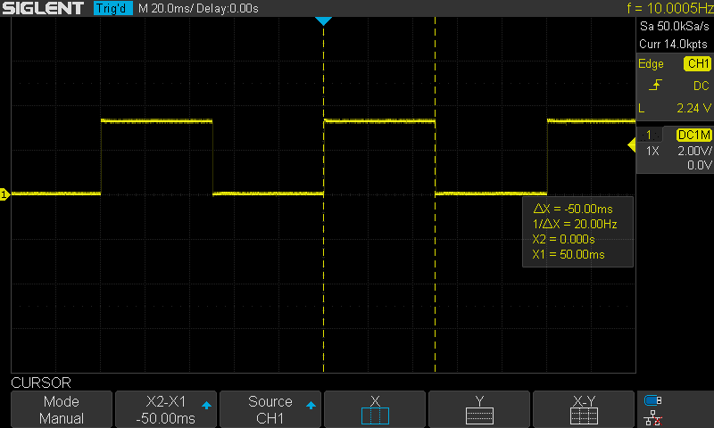
- Set Timer0 to generate a periodic interrupt each 50ms
- In Timer0_IRS() which runs every 50ms, do a LED toggle
- Keep repeating…
ESP32 Timer Interrupt – Arduino Code Example
To generate a periodic interrupt every 50ms, we need to set the timer’s prescaler value and the alarm register’s value (TimerTicks) as well. Therefore, we need to recall the ESP32 Timer’s equation.
![]()
TOUT is desired to be 50ms. The APB_CLK has a default value of 80MHz. So let’s set the prescaler to 80, and solve for TimerTicks. Which therefore will turn out to be:
TimerTicks=50,000
Hence, we’ll set all of this in our code and give it a test!
Prescaler = 80
TimerTicks (AlarmValue) = 50,000
The Full code Listing
|
1 2 3 4 5 6 7 8 9 10 11 12 13 14 15 16 17 18 19 20 21 22 23 24 25 26 |
/* * LAB: 25 * Name: ESP32 Timer Interrupt Example * Author: Khaled Magdy * For More Info Visit: www.DeepBlueMbedded.com */ #define LED 21 hw_timer_t *Timer0_Cfg = NULL; void IRAM_ATTR Timer0_ISR() { digitalWrite(LED, !digitalRead(LED)); } void setup() { pinMode(LED, OUTPUT); Timer0_Cfg = timerBegin(0, 80, true); timerAttachInterrupt(Timer0_Cfg, &Timer0_ISR, true); timerAlarmWrite(Timer0_Cfg, 50000, true); timerAlarmEnable(Timer0_Cfg); } void loop() { // Do Nothing! } |
Choose the board, and COM port, hold down the BOOT button, click upload and keep your finger on the BOOT button pressed. When the Arduino IDE starts sending the code, you can release the button and wait for the flashing process to be completed. Now, the ESP32 is flashed with the new firmware.
Hardware Connections
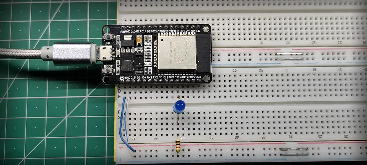
The Result of This LAB
ESP32 Frequency Counter With Timer & Interrupt
| LAB Number | 26 |
| LAB Name | ESP32 Frequency Counter With Timer, Interrupt, and I2C LCD Display |
- Include the libraries
- Define an object of LiquidCrystal_I2C, set its parameters, and initialize the LCD
- Initialize Timer0 with minimum prescaler value (2)
- Initialize an input pin with external interrupt enabled
- In the external interrupt handler: get the time between every two rising edges and use it to get the frequency in Hz. [ Frequency = 1/Period ].
- Print the measured frequency to the I2C LCD display
- Keep repeating…
ESP32 Frequency Counter With I2C LCD – Arduino Code
The Full code Listing
|
1 2 3 4 5 6 7 8 9 10 11 12 13 14 15 16 17 18 19 20 21 22 23 24 25 26 27 28 29 30 31 32 33 34 35 36 37 38 39 40 41 42 43 44 45 46 47 48 49 50 51 52 53 54 55 56 57 58 59 60 61 62 63 64 65 66 67 |
/* * LAB: 26 * Name: ESP32 Timers Interrupts LAB (Frequency Counter) * Author: Khaled Magdy * For More Info Visit: www.DeepBlueMbedded.com */ #include <Wire.h> #include <LiquidCrystal_I2C.h> #define IN_SIGNAL_GPIO 35 LiquidCrystal_I2C I2C_LCD1(0x27, 16, 2); // set the LCD address to 0x27 for a 16 chars and 2 line display hw_timer_t *Timer0_Cfg = NULL; bool Measurement_InProgress = false; uint64_t Measured_Time = 0; uint64_t Measured_Freq = 0; void IRAM_ATTR Ext_INT1_ISR() { if(Measurement_InProgress == false) { Measurement_InProgress = true; timerWrite(Timer0_Cfg, 0); timerStart(Timer0_Cfg); } else { Measured_Time = timerRead(Timer0_Cfg); timerStop(Timer0_Cfg); Measurement_InProgress = false; if(Measured_Time == 0) { Measured_Freq = 0; } else { Measured_Freq = (40000000/Measured_Time); } } } void setup() { // Initialize The I2C LCD I2C_LCD1.begin(); // Turn ON The Backlight I2C_LCD1.backlight(); // Enable External Interrupt Pin pinMode(IN_SIGNAL_GPIO, INPUT); attachInterrupt(IN_SIGNAL_GPIO, Ext_INT1_ISR, RISING); // Configure Timer0 Timer0_Cfg = timerBegin(0, 2, true); } void loop() { // Print The Reading To LCD I2C_LCD1.clear(); I2C_LCD1.setCursor(0, 0); I2C_LCD1.print("Measured Freq: "); I2C_LCD1.setCursor(0, 1); I2C_LCD1.print(Measured_Freq); I2C_LCD1.print(" Hz"); delay(250); } |
Choose the board, COM port, hold down the BOOT button, click upload and keep your finger on the BOOT button pressed. When the Arduino IDE starts sending the code, you can release the button and wait for the flashing process to be completed. Now, the ESP32 is flashed with the new firmware.
The connection between ESP32 & I2C LCD module should be as follows.
| PCF8574 I2C LCD Module | ESP32 DevKit v1 Board |
| SCL | GPIO22 |
| SDA | GPIO21 |
| Vcc | Vin |
| GND | GND |
The input signal pin is defined as D35 as you can see in the connections down below. The “White” wire going to D35 is the input signal to be measured.
Note: the target may halt when you start the application with an external signal already connected to the input measurement pin. You can disconnect it, reset the ESP32 board, Reconnect the input signal again, and it’s going to pick up the incoming signal and print its frequency on the LCD.
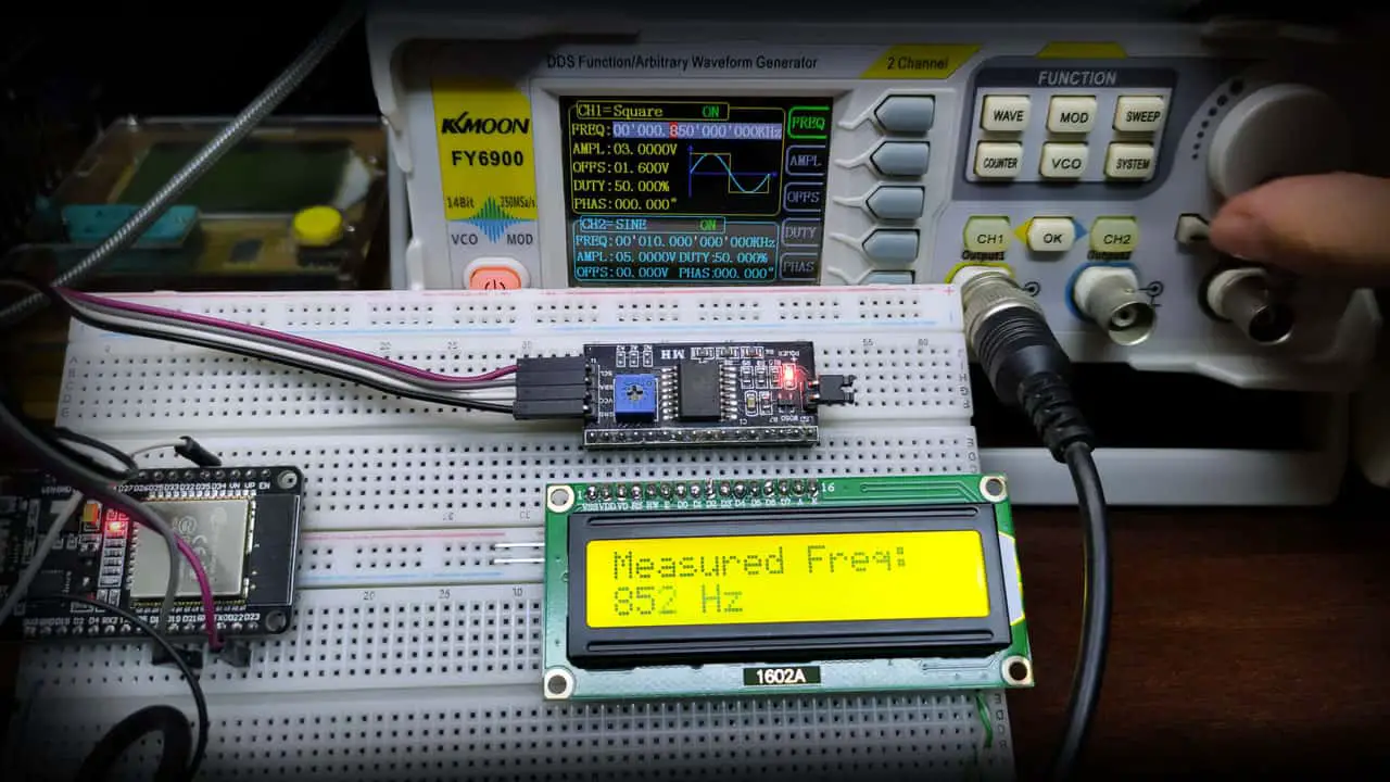
Here is The Result
Concluding Remarks: it’s not ideal in many aspects but it’s simple enough to clarify the potential use case for the timer peripheral in measuring the elapsed time between two different events. Not to mention how bad the readings become when the input frequency goes up to 100kHz and beyond. Or even the fact that at 50kHz input signal, the CPU will be receiving and handling 50,000 interrupts per second! which is a very bad design decision in the first place. The whole application clarifies the functionality of timer modules and highlights the PCNT (pulse counter) which is the better alternative for this application. The PCNT is a peripheral integrated into ESP32 as well, which we’ll be discussing in a future tutorial.
Concluding Remarks For ESP32 Timers
ESP32 Timer Code Compilation Error
You may get a compilation error for the following line of code
|
1 |
hw_timer_t *Timer0_Cfg = NULL; |
as hw_timer is not defined in the Arduino core itself. And all ESP32 timer APIs of course. Just make sure that you’ve selected the ESP32 board from the tools menu. This will auto-include the ESP32 header files into the Arduino core and it’s going to compile just as fine.
ESP32 Timer Resolution
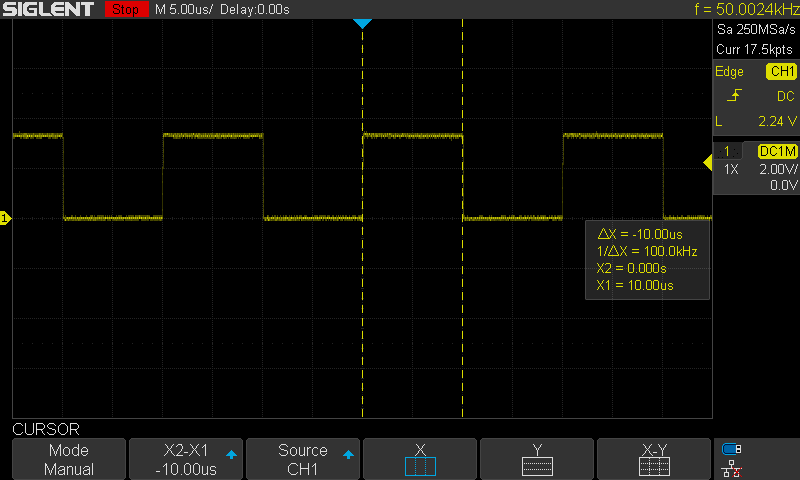
The ESP32 timers are generally 64bit in resolution. This can also be expressed in terms of the timer’s minimum tick time. Which happens to be the tick time when you set the prescaler value to its minimum. This can be achieved by writing 1 or 2 in the prescaler value. This will result in a TickTime = 2/80MHz = 25ns.
I could achieve a 10μs periodic interrupt generation with the following code and you can see the results on my oscilloscope down below.
|
1 2 3 4 5 6 7 8 9 10 11 12 13 14 15 16 17 18 19 |
#define LED 21 hw_timer_t *Timer0_Cfg = NULL; void IRAM_ATTR Timer0_ISR() { digitalWrite(LED, !digitalRead(LED)); } void setup() { pinMode(LED, OUTPUT); Timer0_Cfg = timerBegin(0, 80, true); timerAttachInterrupt(Timer0_Cfg, &Timer0_ISR, true); timerAlarmWrite(Timer0_Cfg, 10, true); timerAlarmEnable(Timer0_Cfg); } void loop() { // Do Nothing! } |
Related Tutorials Based On ESP32 Timers
- ESP32 Audio Signal Generation
- ESP32 Motor Control
- And More…
Learn More About Timers
- Timers in PIC Microcontrollers
- Why To Use Timers instead of Delay? [Article]
- Timers in STM32 ARM Microcontrollers
You can also check the ESP32 Course Home Page ???? for more ESP32 tutorials divided into sections based on categories. This may be helpful for you in case of searching for a specific tutorial or application.
Download Attachments
You can download all attachment files for this Article/Tutorial (project files, schematics, code, etc..) using the link below. Please consider supporting my work through the various support options listed in the link down below. Every small donation helps to keep this website up and running and ultimately supports our community.