| Previous Tutorial | Tutorial 24 | Next Tutorial | |||||
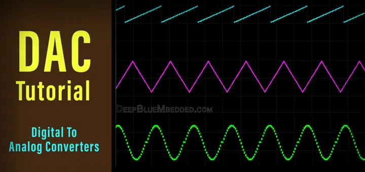
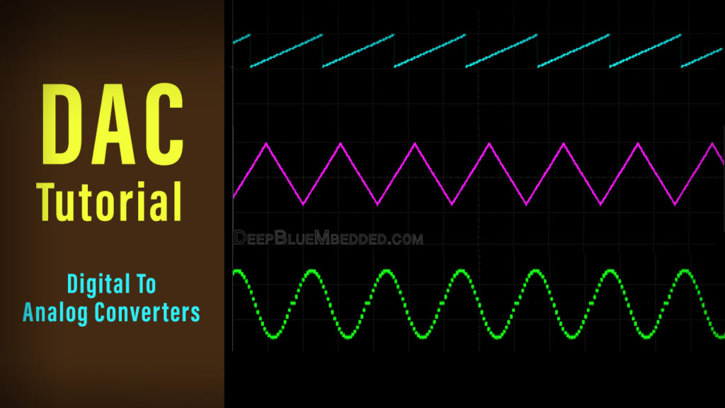
| Digital To Analog Converter (DAC) & Waveform Generation | |||||||
| Introductory Level ★☆☆☆☆ | |||||||
In this tutorial, you’ll learn the basics of digital to analog converters DACs. What’s A DAC? How DACs Work? And What are the common types of DACs? And which to use for our projects.
This tutorial includes 4 practical LABs/Projects on generating analog voltages using a DAC. As well as generating analog waveforms @ any desired frequency (e.g Sawtooth, Triangular, and Sin Wave). This is also how we generate basic sound tones using microcontrollers.
It’s going to be an enjoyable tutorial however, combining light-weight theory, many tips, notes, and interesting practice LABs. So Let’s Get Started!
[toc]
Components Needed For This Tutorial
| Qty. | Component Name | Buy On Amazon.com |
| 1 | PIC16F877A | Add |
| 1 | BreadBoard | Add |
| 1 | Resistor Kit | Add Add |
| 1 | DSO (Digital Storage Oscilloscope) | Add Add |
| 1 | Jumper Wires Pack | Add Add |
| 1 | LM7805 Voltage Regulator (5v) | Add |
| 1 | 4MHz Crystal Oscillator | Add |
| 1 | PICkit2 or 3 Programmer | Add |
What’s A Digital-To-Analog Converter | DAC?
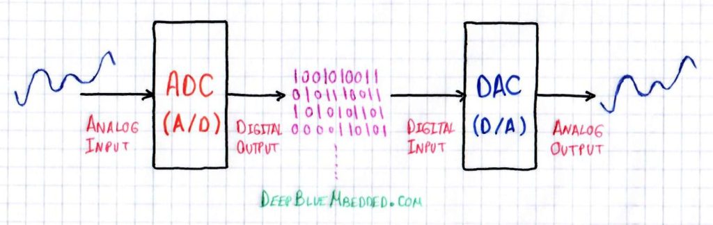
In Electronics, a digital-to-analog converter (DAC or D/A) is an electronic circuit that converts digital data (0’s & 1’s) to an analog signal. Functionally, it’s the inverse of the ADC (analog-to-digital converter). And A DAC is remarkably cheaper than ADC by orders of magnitude.
DACs are commonly used for analog waveform generation applications such as audio/music players, video players, TVs, and various electronic systems. Many ADCs include a DAC as a building block of their structures in fact.
As in ADC, there is quantization noise in the signal due to the fact that a DAC is converting a discrete digital data to corresponding analog voltage levels. So, there is inherent quantization noise at a rate equal to the sampling rate of the DAC.
As stated in Nyquist-Shannon sampling theorem, a DAC can be used to reconstruct an analog signal from digital data samples (captured by an ADC). As long as the bandwidth is less than Nyquist frequency (No violation to Nyquist sampling theorem). A reconstruction filter can be used to reduce quantization noise appearing at the analog output.
<< Don’t Forget To Check Out The ADC Tutorial >>
Why Do We Need DACs?
We need digital to analog converters (DACs) in different applications of digital computers. Digital computers store, manipulate, read in, and send out Digital Data (0’s & 1’s). So there should be a way to convert the digital representation back to analog signals.
Audio files are stored as digital data in the memory of a computer and in order to play it back, it should be converted back to an analog signal. Another situation in which we need DACs is analog control systems. A digital computer can monitor a process and run the instructions of a control algorithm. But in order to send out the output of the control algorithm to actuators, it should be converted to an analog voltage and here DACs come to play.
Applications Of DAC
Digital To Analog Converters (DACs) are being used in a very wide range of applications whether it’s required to have a basic D/A conversion or a much more precise D/A conversion. Some applications demand a high-frequency sampling rate for the DAC while others are demanding high-resolution DACs. And many other applications need to balance between high-frequency and resolution trade-off.
Typical applications of DACs include, but not limited to, the following:
- Audio/Music Players
- Video Players
- Control Systems
- ADC (A/D)
- Synthesizers
- Radar Systems
- Waveform Generators
- Oscilloscopes & instruments
- Power Supplies
- DDS (Direct Digital Synthesizers)
- DDS (Data Distribution Systems)
- And Much More…
Types Of DACs
1. Binary Weighted DAC
The Binary-Weighted DAC contains individual electrical components for each bit of the DAC connected to a summing point. Each input in the summing has powers-of-two values with most current or voltage at the most-significant bit. These precise voltages or currents sum to the correct output value. This is one of the fastest conversion methods but suffers from poor accuracy because of the high precision required for each individual voltage or current. The most common DACs of this type are the following:
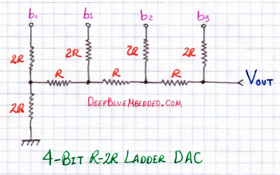
R-2R Ladder DAC, which is a binary-weighted DAC that uses a repeating cascaded structure of resistor values R and 2R. This improves the precision due to the relative ease of producing equal valued-matched resistors. It’s the cheapest, yet easiest, DAC you can build on your own.
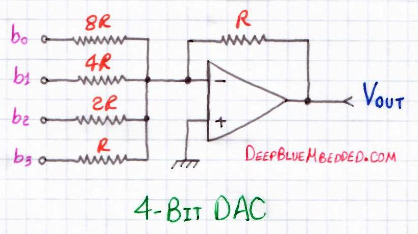
Binary Summing Amplifier DAC is basically an op-amp in summing configuration. With multiple resistors connected to one input. The junction where the resistors meet is called the summing junction or the virtual ground. The binary input goes into the resistors and the analog output is obtained on the output of the op-amp. The values of these resistors are chosen carefully to produce a binary-weighted summation for the digital inputs.
2. PWM DAC
The pulse width modulating DAC is typically a PWM generator running @ pretty high-frequency range. The analog voltage level at the output could be easily obtained by averaging the PWM signal. In technical terms, we’ll filter out the high-frequency component of the PWM signal to leave only the average DC component. A simple low-pass filter could do the job. All in all, it’s an efficient way to create a DAC but requires more effort to get clean output.
We’ll discuss this method of creating DACs in much more detail in the future. So, stay tuned for that!
3. Successive Approximation (Cyclic) DAC
Cyclic DAC which successively constructs the output during each cycle. Individual bits of the digital input are processed each cycle until the entire input is accounted for.
Using A DAC With Microcontrollers
In this section, we’ll see how can you use a DAC with your microcontroller. There are many different ways in which you can get a DAC depending on your application’s needs. The available options to add a DAC output to your microcontroller-based system include the following:
1. R-2R Ladder DAC
This is probably the easiest & cheapest way to get a DAC and connect its inputs to your microcontroller. Building an R-2R ladder is rather simple, all you need is a few resistors of R and 2R (e.g. 1k&2k or 5k&10k, and so on). Here is the schematic diagram for the R-2R ladder (assuming 4-bit DAC). You can continue connecting resistors in the same manner to get 10-Bit or 12-Bit DAC.
2. Binary Weighted-Summing DAC
You can also create a simple DAC with an Op-Amp in weighted-summing configuration and get a resolution up to 8-Bit. Here is a schematic diagram for a binary weighted-summing op-amp 4-Bit DAC
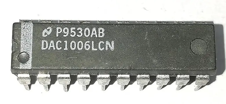
3. Serial/Parallel DAC IC
Another option is to get a high-precision (resolution) DAC ic chip and interface it with your microcontroller. There are serial DACs (typically SPI bus) for reduced required pin count of MCU. And there are also parallel DAC ICs which you can use if it fits well in your application’s design specifications.
4. PWM As DAC
Another considerable option is to use one of your microcontroller’s PWM output pins as a DAC. By varying the duty cycle of the PWM, the average output voltage varies correspondingly. In order to get an “averaged” output or filtered, you’ll need to set a high-frequency PWM and filter it out with a low-pass filter. The result is a quite clean DC voltage level which corresponds to the Duty Cycle % of the PWM.
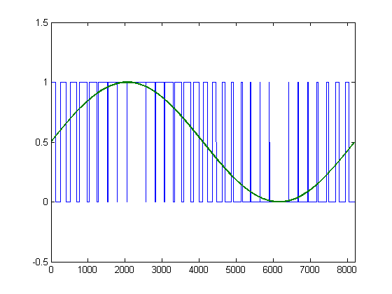
Varying the PWM’s Duty Cycle following a digital sine table will result in an analog sinusoidal waveform as shown in the figure below. Please, note that this method won’t be completely discussed in this tutorial. Instead, we’ll make a simple R2R ladder and PWM DAC will be discussed separately in the future!
5. Integrated DAC Module
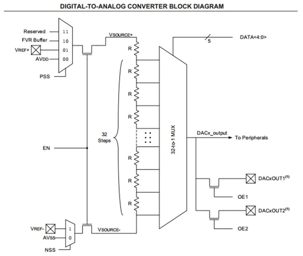
Well, in fact, nowadays there are so many microcontrollers are being manufactured with a DAC module integrated within! it’s a cool feature which provides you the flexibility to configure it internally without needing to connect anything outside the microcontroller and reduce the overhead as long as you need a moderate DAC output. Unless you need some specific requirements for the DAC output, then you might consider searching for a convenient separate DAC IC.
Here is the block diagram of a DAC Module within a relatively new PIC microcontroller.
Generating Adjustable Analog Voltage – LAB1
| Lab Name | Generating Adjustable Analog Voltage With DAC |
| Lab Number | 24 |
| Lab Level | Beginner |
| Lab Objectives | Learn how to configure The ADC Module and read analog signals. And Transfer the digital output of the ADC to the input of a DAC to reconstruct the analog signal once again. And build the R-2R ladder DAC circuit on breadboard & test out everything |
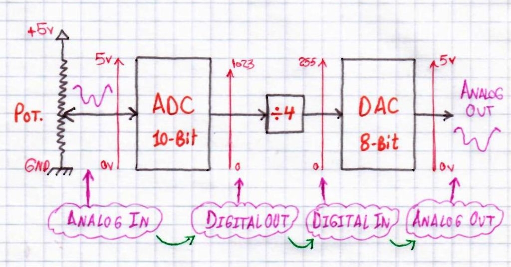
This is The Functional Description Of The System We’ll Be Building
1. Coding
Open the MPLAB IDE and create a new project name it “Analog_Out_DAC”. If you have some issues doing so, you can always refer to the previous tutorial using the link below.

Set the configuration bits to match the generic setting which we’ve stated earlier. And if you also find troubles creating this file, you can always refer to the previous tutorial using the link below.

Now, open the main.c file and let’s start developing the firmware for our project.
Here is the Full Code Listing For This LAB
|
1 2 3 4 5 6 7 8 9 10 11 12 13 14 15 16 17 18 19 20 21 22 23 24 25 26 27 28 29 30 31 32 33 34 35 36 37 38 39 40 41 42 43 44 45 46 47 48 49 50 51 |
/* * File: main.c * LAB Name: Generating Analog Out With DAC * LAB Number: 24 * Author: Khaled Magdy * Visit My Website @ https://deepbluembedded.com */ #include <xc.h> #include "config.h" #include <stdint.h> #define _XTAL_FREQ 4000000 #define DAC_OUT PORTB void ADC_Init(); uint16_t ADC_Read(uint8_t); //--------------------------------------------------- //------------------[ Main Routine ]----------------- void main(void) { ADC_Init(); TRISB = 0x00; // For 8-Bit DAC Out DAC_OUT = 0x00; uint16_t AN0RES; while(1) { AN0RES = ADC_Read(0)>>2; // DAC_OUT = (10bit ADC Result) / 4 = [ 0->255 ] DAC_OUT = AN0RES; // Transfer Data To DAC __delay_ms(1); // Reduce CPU Loading For Better Simulation } return; } //--------------------------------------------------- //------------[ AD Converter Routines ]-------------- void ADC_Init() { ADCON0 = 0x41; // Turn ADC ON, Select AN0 Channel, ADC Clock = Fosc/8 ADCON1 = 0x80; // All 8 Channels Are Analog, Result is "Right-Justified" // ADC Clock = Fosc/8 } uint16_t ADC_Read(uint8_t ANC) { if(ANC<0 || ANC>7) // Check Channel Number Validity { return 0;} ADCON0 &= 0x11000101; // Clear The Channel Selection Bits ADCON0 |= ANC<<3; // Select The Required Channel (ANC) // Wait The Aquisition Time __delay_us(30); // The Minimum Tacq = 20us, So That should be enough GO_DONE = 1; // Start A/D Conversion while(ADCON0bits.GO_DONE); // Polling GO_DONE Bit // Provides Delay Until Conversion Is Complete return ((ADRESH << 8) + ADRESL); // Return The Right-Justified 10-Bit Result } |
2. Simulation
Here is an animation for the running simulation tests.
Yes, it seems like a kind of trolling around to feed in an analog input voltage to an ADC and reconstruct it back once again using a DAC. We’re not doing something useful and It’s not the best way to get an adjustable Vout. But it’s just the beginning to make you familiar with the operation of a Digital To Analog Converter (DAC)! The next LABs are much more interesting, however.
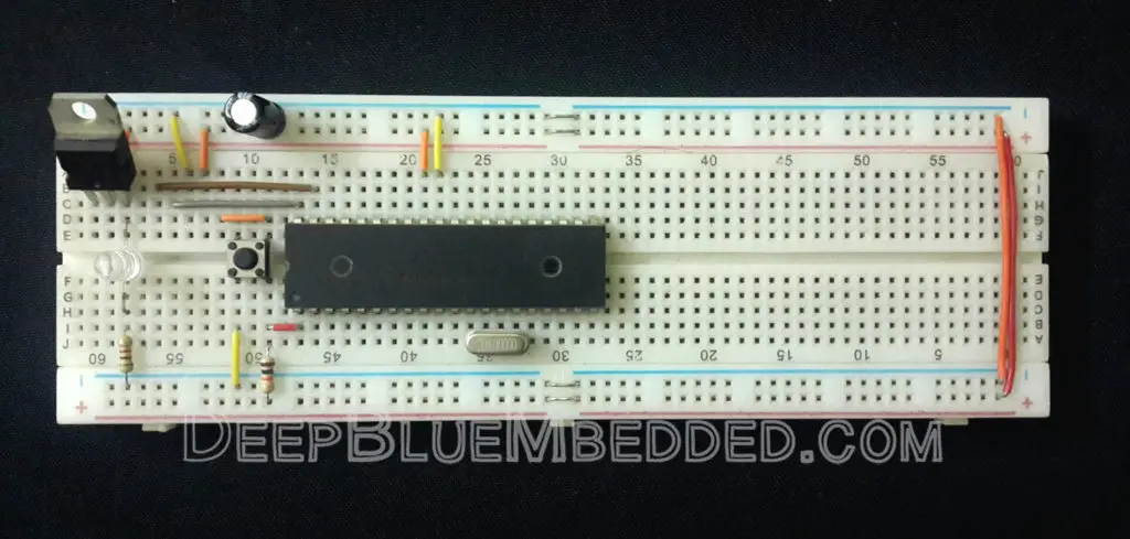
3. Prototyping
Wiring up this schematic on a breadboard should be an easy task. Just upload your firmware hex file to the microcontroller chip. And hook up the input power rails and start testing it out!
Here is a short video for the results of this LAB & verification with AVOmeter.
Setting Sampling Period For Desired Frequency
While generating analog waveforms using a microcontroller & a DAC, it’s desirable to have a controllable output frequency for the analog waveform. The frequency of the output signal is determined by the following formula
![]()
Where Ns is the number of sample points in a single cycle of the waveform. And Ts is the sample period for the DAC. In fact, we control both of those parameters in order to achieve the desired output frequency with an acceptable amount of “Quantization Noise” due to sampling.
Let’s consider a quick practical numeric example to make this more clear.
Example 1
Let’s assume it’s desired to get a sawtooth waveform swinging between (0-5v) @ frequency of 10 Hz.
Well, in order to get a ramp-up in output voltage, the digital output going to the DAC should go from 0 up to 255 which corresponds to a voltage ramp from 0 to 5v.
So, let’s now settle for 256 levels (sample points) in each cycle of the waveform. This can be reduced for increasing the maximum output frequency while sacrificing the “Harmonic Distortion” due to the reduced resolution which increases the quantization noise. All in all, now we’ve Ns = 256
For the desired Fout = 10Hz, the period of each cycle is T = 100ms
The only unknown now is the sampling period Ts. And using the formula shown above, it ends up being
Ts = 100ms/256 = 390μsec
Now, we’re almost done! The C-Code which will generate the desired waveform will be something like this
|
1 2 3 4 5 6 7 8 |
uint8_t counter = 0; while(1) { DAC_OUT = counter++; __delay_us(390); } // Note That When counter==255, it'll overflow in the next cycle of the loop // & rolls-over back to ZERO |
Generating Sawtooth (Ramp) Waveform – LAB2
| Lab Name | Generating Sawtooth Waveform With DAC @ 10Hz |
| Lab Number | 25 |
| Lab Level | Beginner |
| Lab Objectives | Learn how to generate analog waveform (sawtooth) with a microcontroller and a DAC. And how to control the frequency of the output waveform. |
1. Coding
Open the MPLAB IDE and create a new project name it “Sawtooth_Out_DAC”. If you have some issues doing so, you can always refer to the previous tutorial using the link below.
Set the configuration bits to match the generic setting which we’ve stated earlier. And if you also find troubles creating this file, you can always refer to the previous tutorial using the link below.
Now, open the main.c file and let’s start developing the firmware for our project.
Here is the Full Code Listing For This LAB
|
1 2 3 4 5 6 7 8 9 10 11 12 13 14 15 16 17 18 19 20 21 22 23 |
/* * File: main.c * Author: Khaled Magdy * LAB Number: 25 * LAB Name: Sawtooth Generator @100Hz */ #include <xc.h> #include "config.h" #include <stdint.h> #define _XTAL_FREQ 4000000 #define DAC_OUT PORTB void main(void) { TRISB = 0x00; uint8_t counter = 0; while(1) { DAC_OUT = counter++; __delay_us(390); } return; } |
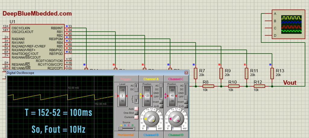
2. Simulation
Here is the simulation result
3. Prototyping
Wiring up this schematic on a breadboard should be an easy task. Just upload your firmware hex file to the microcontroller chip. And hook up the input power rails and start testing it up!
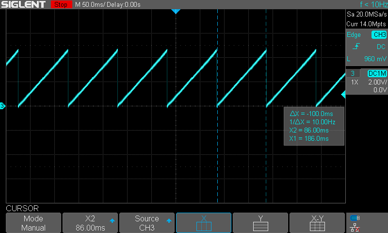
Here is a snapshot on my oscilloscope for the output waveform
Generating Triangular Waveform – LAB3
| Lab Name | Generating Triangular Waveform With DAC @ 10Hz |
| Lab Number | 26 |
| Lab Level | Beginner |
| Lab Objectives | Learn how to generate analog waveform (triangular) with a microcontroller and a DAC. And how to control the frequency of the output waveform. |
In this example, Ns = 256 (ramp-up) + 255 (ramp-down) = 511 sample points. So, the Ts = 100ms/511 = 196μsec
1. Coding
Open the MPLAB IDE and create a new project name it “Traingular_Out_DAC”. If you have some issues doing so, you can always refer to the previous tutorial using the link below.
Set the configuration bits to match the generic setting which we’ve stated earlier. And if you also find troubles creating this file, you can always refer to the previous tutorial using the link below.
Now, open the main.c file and let’s start developing the firmware for our project.
Here is the Full Code Listing For This LAB
|
1 2 3 4 5 6 7 8 9 10 11 12 13 14 15 16 17 18 19 20 21 22 23 24 25 26 27 28 29 30 31 32 |
/* * File: main.c * Author: Khaled Magdy * LAB Number: 26 * LAB Name: Triangular Waveform Generator @ 10Hz */ #include <xc.h> #include "config.h" #include <stdint.h> #define _XTAL_FREQ 4000000 #define DAC_OUT PORTB void main(void) { TRISB = 0x00; DAC_OUT = 0x00; uint8_t counter = 0; while(1) { while(counter < 255) { DAC_OUT = counter++; __delay_us(196); } while(counter > 0) { DAC_OUT = counter--; __delay_us(196); } } return; } |
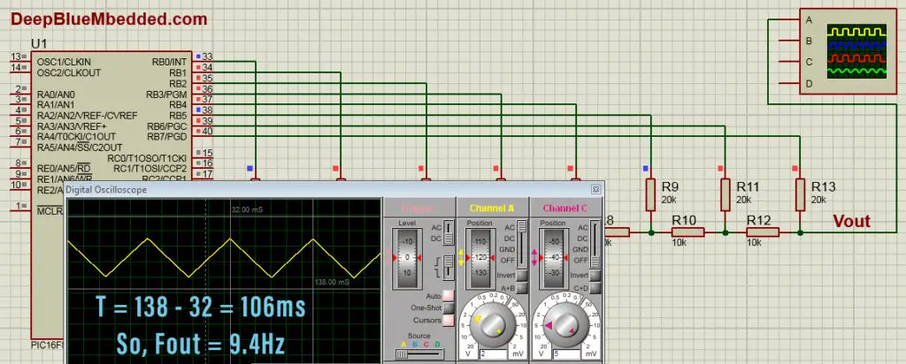
2. Simulation
Here is the simulation result.
3. Prototyping
Wiring up this schematic on a breadboard should be an easy task. Just upload your firmware hex file to the microcontroller chip. And hook up the input power rails and start testing it up!
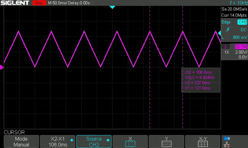
Here is a snapshot for the output on my oscilloscope
Generating Sine Wave With MCU & DAC – LAB4
| Lab Name | Generating Sine Wave With DAC @ 50Hz |
| Lab Number | 27 |
| Lab Level | Beginner |
| Lab Objectives | Learn how to generate analog waveform (Sine) with a microcontroller and a DAC. And how to control the frequency of the output waveform. |
For the last couple of labs, it was sufficient to have a single variable “counter” to create up-counting RAMP waveform and also up-down-counting TRIANGULAR waveform. But for this lab, we’ll need to store a small look-up table for a single cycle SINE wave.
You can calculate it manually with your own calculator or you can also craft a MATLAB script to generate the table for you. But for the sake of simplicity, in this tutorial, I’ll show you how to use the following online calculator to get the sine table. Online Sine Table Generator
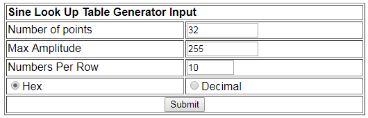
For this tutorial, I’ll only need 32 sample points. The maximum amplitude for the sine wave is 5v which corresponds to 255 as a digital input for the DAC. My DAC is 8-Bit. If you’re using a 10-Bit DAC, this value would be 1023 and so on. Finally, for the last option, I’ve used for convenience and you can get all the values in a single line of code if that’s what you want! Click submit and a table like this will pop-up in your face!
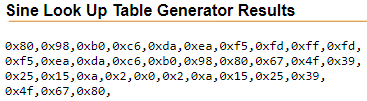
Copy these values to an array in your code and you’re good to go!
To get the sampling period, we’ll calculate it in the same way as the previous LABs. F=50Hz so T = 20ms
Therefore, Ts = 625μsec
1. Coding
Open the MPLAB IDE and create a new project name it “Sine_Out_DAC”. If you have some issues doing so, you can always refer to the previous tutorial using the link below.
Set the configuration bits to match the generic setting which we’ve stated earlier. And if you also find troubles creating this file, you can always refer to the previous tutorial using the link below.
Now, open the main.c file and let’s start developing the firmware for our project.
Here is the Full Code Listing For This LAB
|
1 2 3 4 5 6 7 8 9 10 11 12 13 14 15 16 17 18 19 20 21 22 23 24 25 26 27 28 29 30 31 32 33 34 35 |
/* * File: main.c * Author: Khaled Magdy * LAB Name: Sine Generator With DAC @ 50Hz * LAB Number: 27 * Visit My Website @ https://deepbluembedded.com */ #include <xc.h> #include <stdint.h> #include "config.h" #define DAC_OUT PORTB #define _XTAL_FREQ 4000000 uint8_t SineTable[33] = { 0x80,0x98,0xb0,0xc6,0xda,0xea,0xf5,0xfd,0xff,0xfd, 0xf5,0xea,0xda,0xc6,0xb0,0x98,0x80,0x67,0x4f,0x39, 0x25,0x15,0xa,0x2,0x0,0x2,0xa,0x15,0x25,0x39,0x4f, 0x67,0x80 }; void main(void) { TRISB = 0x00; DAC_OUT = 0x00; uint8_t i=0; while(1) { DAC_OUT = SineTable[i++]; __delay_us(625); if(i == 33) i=0; } return; } |
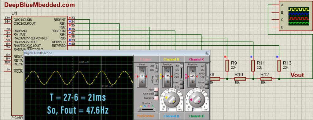
2. Simulation
Here is the simulation’s result.
3. Prototyping
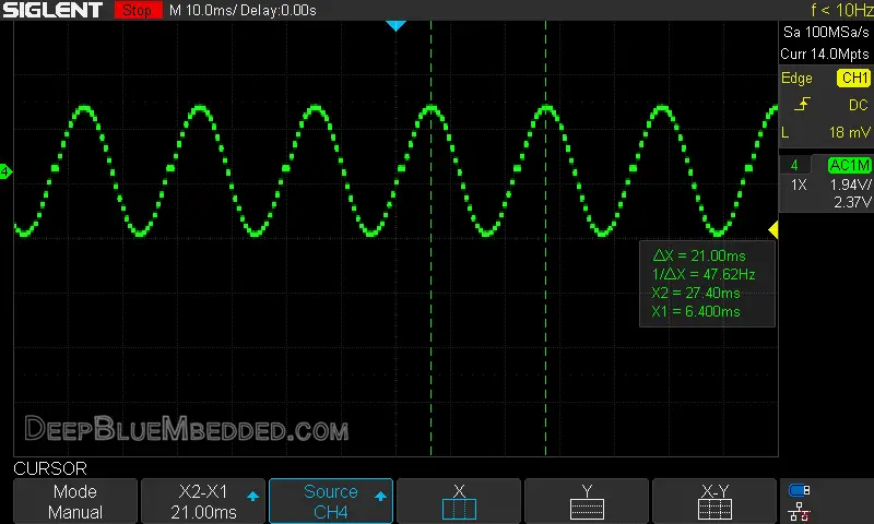
Wiring up this schematic on a breadboard should be an easy task. Just upload your firmware hex file to the microcontroller chip. And hook up the input power rails and start testing it up!
Here is a snapshot for the output on my oscilloscope
|
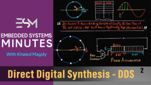
I know the results of all LABs in this tutorial aren’t what you might hope for, in terms of output frequency accuracy. These are just toy examples to show you how a DAC works and how can digital data in your microcontroller’s registers turn into analog waveforms! This topic will be revisited again and in much more detail. We’ll generate analog waveforms with frequency accuracy up to 0.000001 and even more! Stay tuned for the tutorial of Direct Digital Synthesis
|
Concluding Remarks
1
it’s better to set up a timer to schedule Consistently Periodic Data Transfers To The DAC unit without too much of CPU intervention (time waste due to delays). The example codes provided in this tutorial are done in such a way to make it simple & easy for you to understand how DACs work and how analog waveforms could be synthesized digitally using digital microcontrollers. But, for real-world applications, you’ll have to consider this point and take it seriously.
All examples which are shown previously make CPU utilization of 100% You even can’t handle interrupts without disrupting the waveform generation. The CPU can do nothing other than transferring the data to the DAC all the time in order to get the desired analog waveform on the output.
And obviously enough, it’s not the way to do such a thing. But for now, it’s ok!
2
Converting data from the discrete digital domain to a discrete sampled analog signal at fixed (discrete) time intervals will introduce Harmonic Distortion at the analog output side of the DAC, due to sampling quantization noise effect. This is something you’ll have to deal with in order to get a clean analog waveform at the output.
This point will be discussed in great detail in a complete separate tutorial in the near future, so check my website frequently and click the little bill to get notified when something new is published.
3
Theoretically, A DAC’s output will swing between 0v And Vref (typically 5v or 3.3v). However, practical DACs don’t. There will be always a small drift above real zero and a small drop from Vref. More advanced DAC chips are being advertised to have a Rail-To-Rail output which is hopefully close enough to the theoretically ideal DAC.
Did you find this useful? Well, why not share it with your network! Maybe someone else would find it helpful too! If you feel extra generous, you may consider supporting my website
| Previous Tutorial | Tutorial 24 | Next Tutorial | |||||