| Previous Tutorial | Tutorial 29 | Next Tutorial | |||||
| Convert PWM To A DAC – Using PWM To Generate Analog Waveforms | |||||||
| STM32 Course Home Page ???? | |||||||
In this article, we’ll be discussing how to use the PWM module as a DAC to generate analog waveforms like a sine wave, sawtooth, etc. Using the STM32 PWM instead of a DAC which is especially useful for the Blue Pill board (STM32F103C8) which doesn’t have an internal DAC module. Therefore, using the technique we’ll learn today, you’ll be able to generate analog waveforms and audio signals using only 1 GPIO pin “The PWM Output”. So, let’s get right into it!
[toc]
Required Components For LABs
All the example code/LABs/projects in the course are going to be done using those boards below.
- Nucleo32-L432KC (ARM Cortex-M4 @ 80MHz) or (eBay)
- Blue Pill STM32-F103 (ARM Cortex-M3 @ 72MHz) or (eBay)
- ST-Link v2 Debugger or (eBay)
| QTY | Component Name | ???? Amazon.com | ???? eBay.com |
| 2 | BreadBoard | Amazon | eBay |
| 1 | LEDs Kit | Amazon Amazon | eBay |
| 1 | Resistors Kit | Amazon Amazon | eBay |
| 1 | Capacitors Kit | Amazon Amazon | eBay & eBay |
| 2 | Jumper Wires Pack | Amazon Amazon | eBay & eBay |
| 1 | 9v Battery or DC Power Supply | Amazon Amazon Amazon | eBay |
| 1 | Micro USB Cable | Amazon | eBay |
| 1 | Push Buttons | Amazon Amazon | eBay |
★ Check The Full Course Complete Kit List
Some Extremely Useful Test Equipment For Troubleshooting:
- My Digital Storage Oscilloscope (DSO): Siglent SDS1104 (on Amazon.com) (on eBay)
- FeelTech DDS Function Generator: KKMoon FY6900 (on Amazon.com) (on eBay)
- Logic Analyzer (on Amazon.com) (on eBay)
Affiliate Disclosure: When you click on links in this section and make a purchase, this can result in this site earning a commission. Affiliate programs and affiliations include, but are not limited to, the eBay Partner Network (EPN) and Amazon.com.
Intro To Signals, Filtering & Frequency Spectrum
I’d like to start this article with an introduction to the basics of signals and how to view a signal in both the time domain and frequency domain. Almost everyone should be familiar with the time domain representation for signals. It’s the voltage-time plot that represents the voltage change characteristics of a signal in time.
By taking the fast Fourier transform for a signal you can see its components in the frequency domain. Every signal can be broken into single or multiple frequency components (harmonics) as stated by the Fourier theorem. And here is an example of this, consider the sine wave down below in the following diagram.
The sine waveform consists of 2 components (a DC component and an AC component). In time domain it’ll look like the one in the upper part of the diagram. However, if we’d like to see this same signal in the frequency domain, by taking the FFT, it’ll be as shown in the middle part of the diagram. Having a DC component at 0Hz and an AC component at 1KHz on the frequency spectrum. And this plot is called the “Frequency-Domain”.
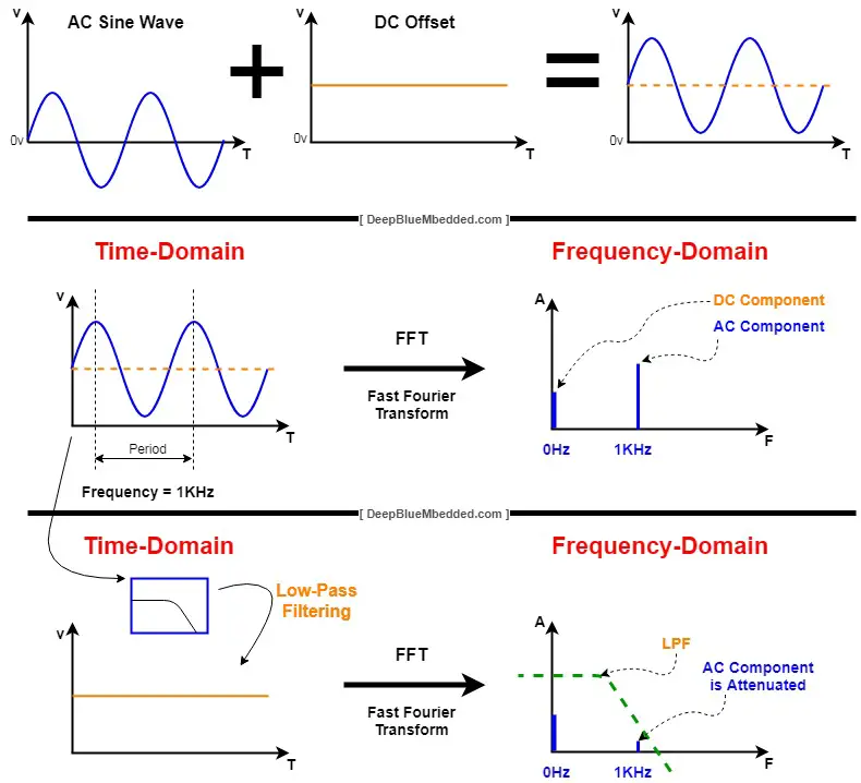
Can we decompose this signal back to its basic components? yes, for sure. Let’s for example take the average voltage (DC component) for this sine wave. This can be achieved by taking this signal as an input to a low-pass filter (LPF) so it filters-out the high-frequency component (The AC sine wave part @ 1KHz) and leaves out the DC average voltage component.
And that’s what you can see in the bottom of the diagram. In the time domain, what is left after low-pass filtering the signal is the DC voltage component (average value). And this can also be viewed in the frequency domain as a significant attenuation in the AC component while the DC component’s magnitude is still the same. That’s the effect of low-pass filtering the signal in both the time & frequency domains.
PWM Signal Characteristics & Filtering
PWM Frequency Spectrum
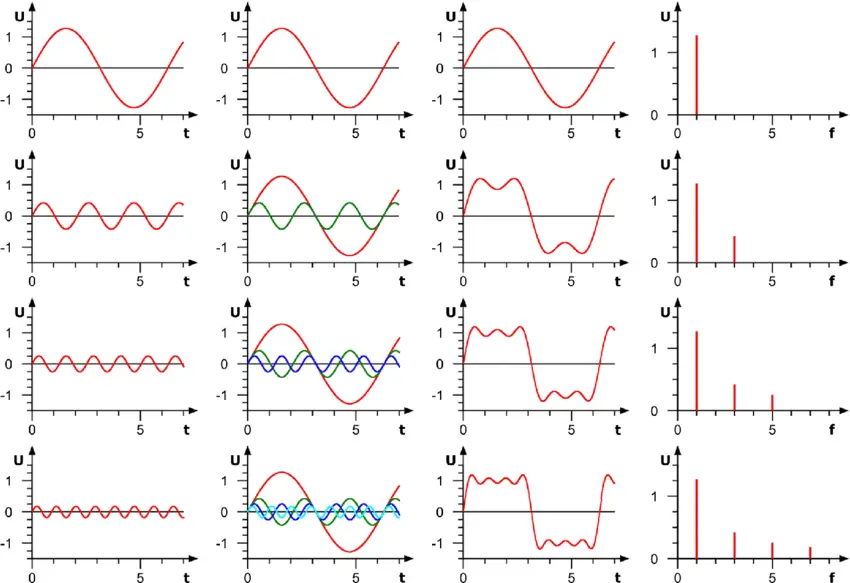
The PWM signal is essentially a square wave whose duty cycle can be adjusted from time to time. The frequency spectrum for a PWM (square wave) is a wide-band spectrum as it does have an infinite number of harmonics. Due to the Fourier theorem, any signal can be decomposed into a summation of sines and cosines of multiple frequencies (also called harmonics), the square wave has an infinite number of harmonics (sine waves at multiple frequencies). As you can see in the following diagram.
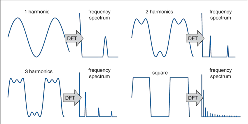
The more harmonics we add, the more it looks like a “good-looking” square wave. So, it has a wide-band spectrum as stated before. The following diagram also confirms this point graphically.
PWM Filtering
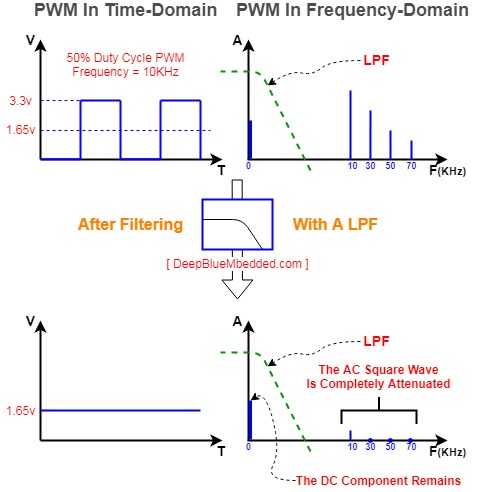
The PWM duty cycle can be seen as the average voltage of a given PWM waveform. For example, a 3.3v PWM signal with a 50% duty cycle can be seen as an average of 1.65v. However, the signal is actually not a constant DC level. It’s fluctuating in time between 0v and 3.3v.
Actuators like motors, speakers, etc tend to have an LPF (low-pass filter) characteristics. So, a motor will change its speed corresponding to the PWM duty cycle change. However, and if we are building a DAC using this PWM signal, we actually need to completely get rid of these PWM AC components (harmonics).
We want the DAC output to be the PWM average voltage value with too little ripple to be acceptable for us. To meet this goal, we always prefer to choose high PWM frequency and low Fc for the LPF so that we get a stable DC output (PWM’s average voltage) out of the LPF.
Another point to note here which is extremely important is that the way this LFP is setup makes it cut-off any AC signal on the output. The output swing is too slow due to the LFP high time constant effect. This will limit the ability to use the PWM-To-DAC system for generating AC signals like sine waves of whatever.
Therefore, there is always a trade-off between the PWM frequency, the output signals frequency FBW, and the LPF characteristics. And that’s what we’re going to investigate in the next section for design steps and in the next tutorial as well to generate waveforms using this PWM-To-DAC technique.
Designing PWM To DAC System
1- Decide On The Required Resolution
The first step in designing a PWM-To-DAC system is to decide on the required DAC resolution. Note that the resolution is the number of discrete voltage levels that the DAC can possibly have and that number is inherited from the PWM itself. The PWM resolution defines how many discrete duty cycle levels there will be, and therefore, the DAC resolution is defined by the used PWM’s resolution.
It’s important to note that the PWM’s resolution stated in the datasheet is not constant. It does change in run time depending on the FPWM frequency you’re operating on. The higher the FPWM, the lower the resolution gets. Therefore, deciding the DAC’s required resolution helps us to set an upper limit for the FPWM.
As stated earlier, the FPWM is desired to be very high enough so that the filtering process can be more effective and results in a lower output ripple. But raising the FPWM will degrade the resolution. That’s why this first step is so important.
2- PWM Frequency Selection
A rule of thumb is to choose the FPWM to be some order of magnitudes larger than the desired output signal’s frequency FBW. The larger the factor k the better.
![]()
And also keep in mind that raising the FPWM will degrade the final DAC’s resolution. As you can see from the formula down below. This indicates that raising the FPWM will decrease its resolution at any value for timer clock FCLK, and therefore the DAC’s resolution decreases as well.

The formula to be used in configuring the timer module in PWM mode to control the PWM output frequency.
![]()
3- RC LPF Design
This step is the most critical step in the design process. As it defines the dynamic characteristics of the resulting DAC system at the end. The LPF filter introduces some delay due to the time constant that can limit the DAC’s ability to swing very quickly to follow a specific waveform pattern.
Therefore, you’ve to carefully choose the frequency response parameters for the LPF while designing it. I can divide the resulting DACs using this technique into two categories: static DACs, dynamic DACs. The static ones do have a heavy LPF with a cut-off frequency at 10Hz may be or 1Hz. With a very slow output swing and it’s convenient in some applications where certain voltage levels need to be sent as an output.
On the other hand, dynamic DACs are used to generate analog waveforms like sine, sawtooth, etc. And the LPF should be designed so as to pass the frequency of the desired signal FBW while blocking the FPWM harmonics. And the following formula is used for this case.
![]()
Choose the resistor R depending on the GPIO pin output driving capability and solve for C to find the capacitor value. And you can calculate the attenuation using the following formula. And if the attenuation is not sufficient, you’ll have to increase the k factor.
![]()
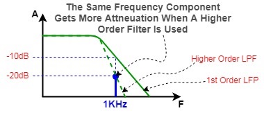
you can customize the filter’s design to meet your application’s criteria. You can use a high order filter that has a sharper roll-off so it filters out the PWM signal in a stronger manner.
4- DAC Output Voltage Control
Controlling the DAC’s output is an easy process, it’s done by changing the duty cycle and that’s it.
![]()
PWM DAC Output Voltage = 3.3 x (CCRx/ARRx)
5- PWM-To-DAC Output Buffering
As I’ve demonstrated earlier in the previous tutorial, it’s required to buffer the DAC’s output before you can send this signal to any electronic circuit. And show you this example below that illustrates the loading effect and the role of the buffer to stabilize the DAC output pin.
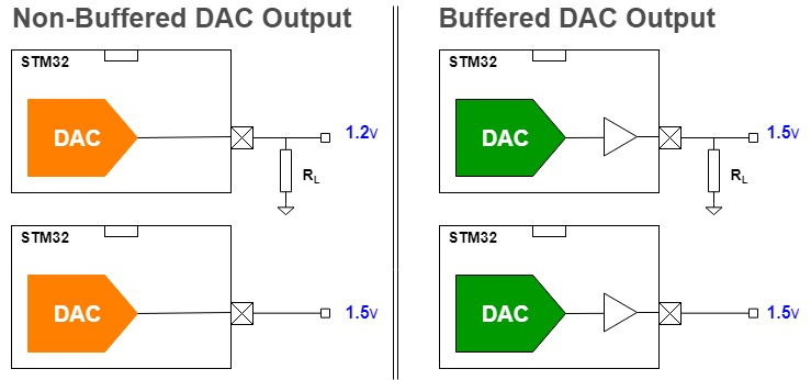
For the PWM-To-DAC technique, it’s still important to buffer the output signal as well.
STM32 PWM To DAC – LAB24
| LAB Number | 24 |
| LAB Title | STM32 PWM To DAC |
- Set up a new project as usual with system clock @ 72MHz
- Set up the timer2 peripheral to operate in PWM mode
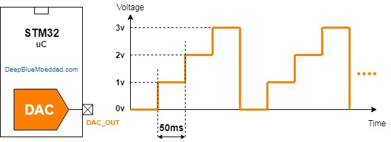
- Change the PWM’s duty cycle to change the output voltage to follow the pattern below
Design Steps:
1- Decide on the required resolution
I want the resulting DAC to have 10-Bits of resolution
2- PWM Frequency Selection
To guarantee a 10-Bit of resolution, the FPWM should be 70312 from this formula
By using the following equation, we can solve for the ARR value that gives us the FPWM required (70.3KHz)
![]()
let PSC = 0, therefore ARR = 1023
And it should be expected as we’ve selected the FPWM in order to guarantee a 10-Bit of resolution. And there is no surprise to find out that the maximum value for counts (ARR register) is 1023.
3- The RC Filter Design
it’ll be a simple RC filter with a cut-off frequency 480Hz. C = 1uF, R = 330 ohm
4- Output Voltage Control
we’d like to output the following voltage pattern 0v, 1v, 2v, 3v, and repeat. For this, we need to calculate the CCRx register value that gives us each of the voltage levels. We’ll use for this the following equation
PWM DAC Output Voltage = 3.3 x (CCRx/ARRx)
1v = 3.3 (CCRx/1023) , so CCRx will be 310
And so on for the other voltage levels
And now, let’s build this system step-by-step
Step1: Open CubeMX & Create New Project
Step2: Choose The Target MCU & Double-Click Its Name
STM32F103C8 (Blue Pill)
Step3: Go To The Clock Configuration
Step4: Set The System Clock To Be 72MHz
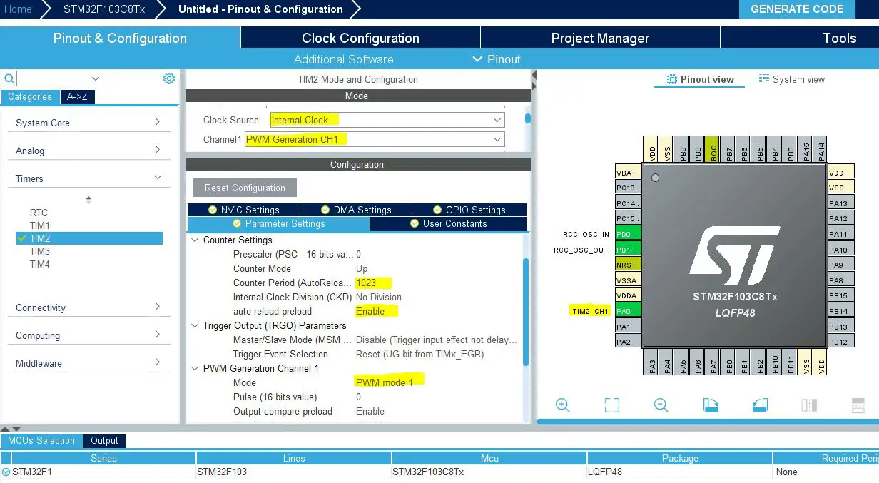
Step5: Now, Configure Timer2 Peripheral In PWM mode As Shown
Step6: Generate The Initialization Code & Open The Project In Your IDE
Here is The Application Code For This LAB (main.c)
|
1 2 3 4 5 6 7 8 9 10 11 12 13 14 15 16 17 18 19 20 21 22 23 24 25 26 27 |
#include "main.h" TIM_HandleTypeDef htim2; void SystemClock_Config(void); static void MX_GPIO_Init(void); static void MX_TIM2_Init(void); int main(void) { uint16_t DAC_OUT[4] = {0, 310, 620, 930}; uint8_t i = 0; HAL_Init(); SystemClock_Config(); MX_GPIO_Init(); MX_TIM2_Init(); HAL_TIM_PWM_Start(&htim2, TIM_CHANNEL_1); while (1) { TIM2->CCR1 = DAC_OUT[i++]; if(i == 4) i = 0; HAL_Delay(50); } } |
Download The STM32 PWM-To-DAC LAB24
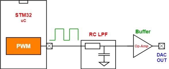
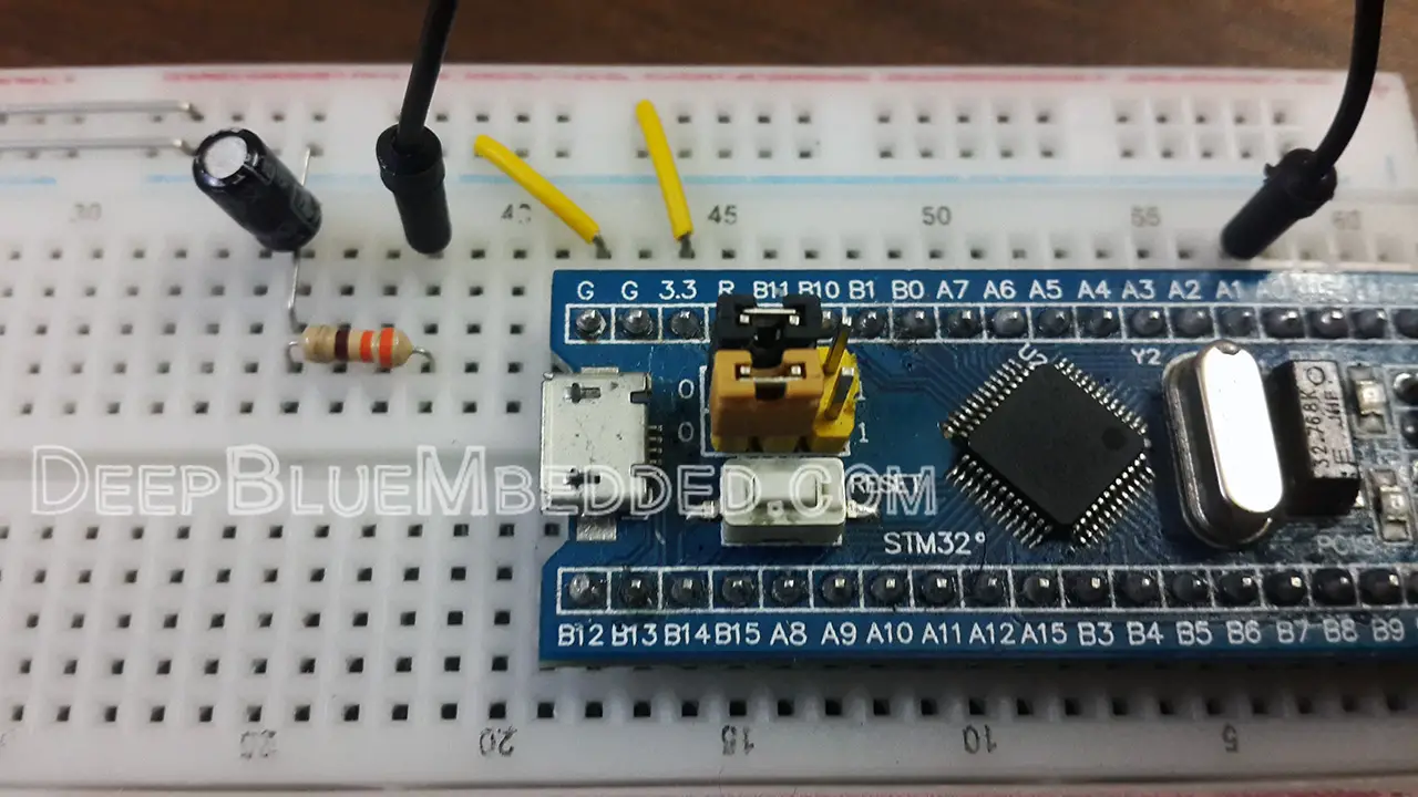
The Hardware Setup
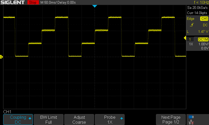
The Result For This LAB Testing On My DSO
Did you find this helpful? If yes, please consider supporting this work and sharing these tutorials!
Stay tuned for the upcoming tutorials and don’t forget to SHARE these tutorials. And consider SUPPORTING this work to keep publishing free content just like this!
| Previous Tutorial | Tutorial 29 | Next Tutorial | |||||