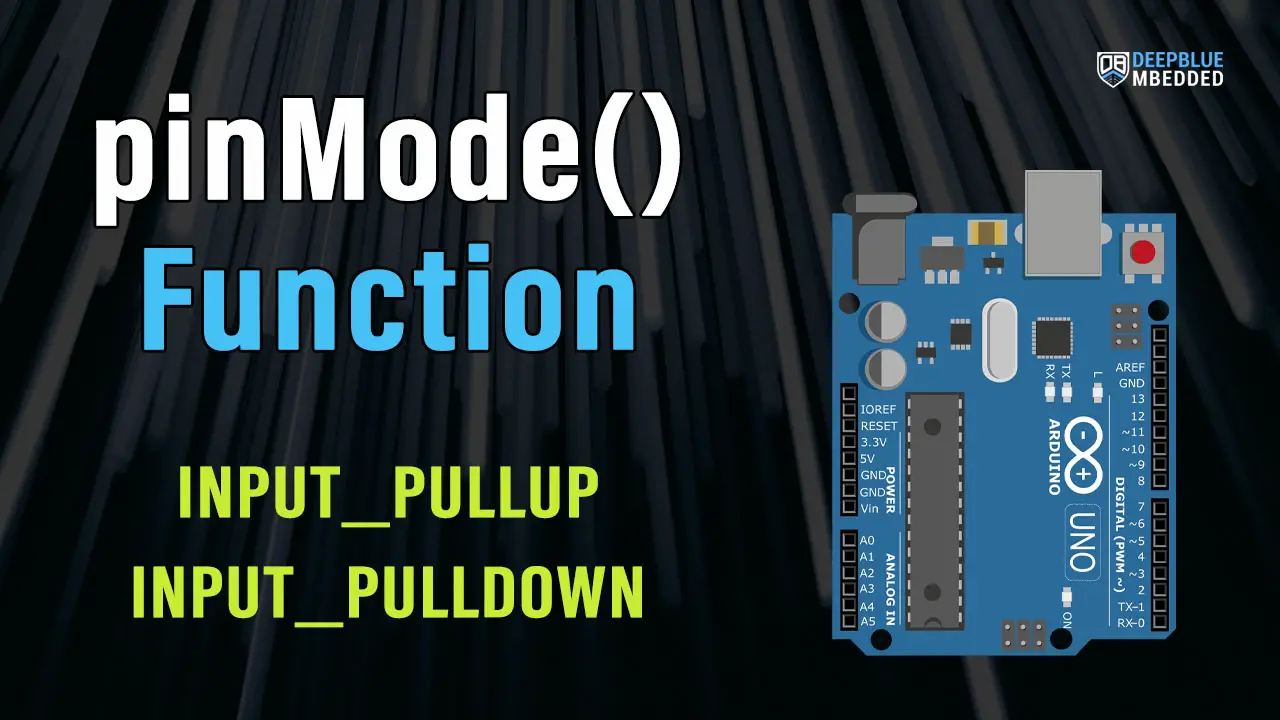
In this tutorial, we’ll discuss the Arduino pinMode() function and INPUT_PULLUP mode in-depth. We’ll start off by explaining the functionality of Arduino pinMode() API. Then, we’ll discuss the Arduino digital IO pin states and why it’s bad to leave a pin floating. Which will drive us to explore the Arduino INPUT_PULLUP internal resistors & INPUT_PULLDOWN as well.
Moreover, we’ll also discuss why and how you shall implement an external Pull-Up or Pull-Down for Arduino input pins near the end of this tutorial. So without further ado, let’s get right into it.
Table of Contents
- Arduino pinMode() Function
- Arduino Digital Pin States
- Arduino INPUT_PULLUP Internal Resistor
- Arduino INPUT_PULLDOWN Internal Resistor
- Arduino External PULLUP & PULLDOWN Resistors
- Arduino pinMode & INPUT_PULLUP Recap
Arduino pinMode() Function
Before using any of the Arduino’s digital IO pins, you first need to call the pinMode() function to define how this IO pin is going to behave during the application runtime (output or input). Typically, we call this function only once within the setup() function for initializign the IO pins we’ll be using within the Arduino sketch later on.
Arduino pinMode Description
The Arduino pinMode() function sets the behavior of a specific digital IO pin to behave as an output pin or an input pin. It can also enable the internal pull-up resistor for input pins if the mode INPUT_PULLUP is selected. However, the mode INPUT will set your IO pin in input mode and explicitly disable the internal pull-up resistor.
pinMode Syntax
|
1 |
pinMode(pin, mode); |
Arduino pinMode Parameters
The Arduino pinMode() function takes only 2 parameters:
- pin: the Arduino pin number to be configured.
- mode: it can be( INPUT, OUTPUT, or INPUT_PULLUP).
There is no INPUT_PULLDOWN macro for Arduino UNO and most other boards. Using INPUT_PULLDOWN mode to enable internal pull-down resistors will cause a compilation error “INPUT_PULLDOWN was not declared in this scope“. However, in Arduino Zero board which supports internal pull-down resistors, you can use this mode and it’ll work.
If you still need an Arduino INPUT_PULLDOWN, you can implement it on your own externally using a resistor. Which we’ll be doing hereafter in this tutorial.
Example Code
The code example below, sets the digital IO pin 8 to be an OUTPUT pin and toggle its state from HIGH to LOW each 1 second.
|
1 2 3 4 5 6 7 8 9 10 |
void setup() { pinMode(8, OUTPUT); // sets the digital pin 8 as output } void loop() { digitalWrite(8, HIGH); // sets the digital pin 8 ON delay(1000); // waits for a second digitalWrite(8, LOW); // sets the digital pin 8 OFF delay(1000); // waits for a second } |
Arduino Digital Pin States
The Arduino’s Digital IO pins can be in one of the following states at any given time:
- HIGH
- LOW
- Hi-Z (High-Impedance mode)
1. Output / HIGH
When the pin is set to be in output mode, it can be driven to a High state (Logic 1) corresponding to an analog voltage level of 5v.
2. Output / LOW
When the pin is set to be in output mode, it can be driven to a Low state (Logic 0) corresponding to an analog voltage level of 0v.
In output mode, the Arduino’s IO pins are able to source or sink up to 40mA of current per IO pin. This is the maximum absolute current that can be sourced from or sunk to any Arduino’s IO pin at any given time. So make sure you’re not over-driving the IO pins in your application.
3. Input (Hi-Z or High-Impedance)
When the IO pin is set to be input, the IO pin will go into Hi-Z mode which means it’s no longer connected to the IO pin output driver. This means it’s not 0 or 1, and the analog voltage on the pin is not predictable and will be susceptible to external noise.

Leaving the digital input pin floating as shown on the left-hand side is pretty bad practice, it’ll pick up a lot of noise, and the GPIO digital logic read units won’t be sure if it’s a 0 or 1. Therefore, we need to do either a pull-up or a pull-down with a 10k resistor as shown on the right-hand side.
The only difference between the pull-up and the pull-down configuration is the logic polarity. But other than that, they’re essentially the same. Note the thin yellow arrow in both configurations. It shows you the dead short circuit path if we didn’t place the 10k resistors.
If somebody pressed the button without this resistor in place, it’ll be a dead short from Vcc to GND. Must it always be a 10k resistor? Of course not! Just use any value to limit the current flow when the button is pressed.
Don’t Leave Input Pins in a Floating (Hi-Z) State
From this, we conclude that when any IO pin is set to be input, it can’t be left in the Hi-Z (or Floating) state. The external noise will disrupt the system behavior and it will no longer be predictable. The solution for this is to make a pull-up or pull-down configuration for your input pin. And we’ll discuss the input Pull-Up & Pull-Down configurations in detail in the next sections.
Arduino INPUT_PULLUP Internal Resistor
As we’ve stated in the previous section when you configure an IO pin to be an input pin for a device like a push button. You must have a pull-up or pull-down resistor in order to eliminate any noise of having the pin floating.
Luckily, the Arduino has internal pull-up resistors for all IO pins as stated in the Atmega328p microcontrollers datasheet. And here is how the IO pin diagram looks.

Each Arduino IO pin has an internal Rpu (pull-up resistor) that can be enabled or disabled using a tiny transistor that connects it to VCC as you can see in the figure above. As well as 2 protection diodes that will clip excessive over/under voltage away from damaging the IO pin.
To enable the Arduino’s internal input pull-up resistor for a specific IO pin (let’s say pin 8), you need to set the mode to be INPUT_PULLUP using the pinMode() function as shown below.
|
1 |
pinMode(8, INPUT_PULLUP); |
And now you can safely connect your push button to pin 8 without having to connect an external pull-up resistor. Here is what it’ll look like at the end.

Arduino INPUT_PULLDOWN Internal Resistor
There is no INPUT_PULLDOWN macro for Arduino UNO and most other boards. Using INPUT_PULLDOWN mode to enable internal pull-down resistors will cause a compilation error “INPUT_PULLDOWN was not declared in this scope“. However, in Arduino Zero board which supports internal pull-down resistors, you can use this mode and it’ll work.
It’s stated clearly in the Atmega328p microcontroller’s datasheet that all IO pins do support an internal pull-up resistor (for input mode) but no mention of internal pull-down resistors which don’t exist in the Atmega328p microcontroller (used in Arduino UNO).
If you still need an Arduino INPUT_PULLDOWN, you can implement it on your own externally using an external pull-down resistor. Which we’ll be doing hereafter in the next section.
Arduino External PULLUP & PULLDOWN Resistors
Despite the fact that you can take advantage of the Arduino’s internal pull-up resistors using INPUT_PULLUP pinMode, you can still however neglect it and connect your own external pull-up or pull-down resistors. And that’s what we’ll be doing next.
Arduino External Input Pull-Up Resistor
In the input pull-up configuration, the Arduino’s input pin will be hooked up to the Vcc with an external resistor (typically 10kΩ). And here is how you’d connect a push button to an Arduino input pin with an external pull-up resistor.

And here is a code example for how you’d check for the push button state in the input external pull-up configuration.
|
1 2 3 4 5 6 7 8 9 10 11 12 13 14 |
void setup() { pinMode(8, INPUT); } void loop() { if(digitalRead(8) == LOW) { // Button Is Pressed } else // If Pin8 State == HIGH { // Button Is Released } } |
Arduino External Input Pull-Down Resistor
In the input pull-down configuration, the Arduino’s input pin will be hooked up to the GND with an external resistor (typically 10kΩ). And here is how you’d connect a push button to an Arduino input pin with an external pull-down resistor.

And here is a code example for how you’d check for the push button state in the input external pull-down configuration.
|
1 2 3 4 5 6 7 8 9 10 11 12 13 14 |
void setup() { pinMode(8, INPUT); } void loop() { if(digitalRead(8) == HIGH) { // Button Is Pressed } else // If Pin8 State == LOW { // Button Is Released } } |
Arduino Input Pull-Up Vs Pull-Down
There is no fundamental difference between the input pull-up and pull-down configurations other than the logic state of the “IDLE” and “ACTIVE” states. The IDLE state is the default state, and the ACTIVE state is the state of the IO pin when the push button is actively pressed.
For Input Pull-Up Configuration:
- IDLE State: HIGH
- Active State: LOW
For Input Pull-Down Configuration:
- IDLE State: LOW
- Active State: HIGH
This is the only difference between both configurations which will affect the way you’ll be checking the pin input value in your code.
Arduino pinMode & INPUT_PULLUP Recap
To conclude this tutorial, we’ll highlight the fact that Arduino pinMode() function is fundamental for any project where you need to control the digital IO pins. You have to first call the pinMode() function to determine whether a specific pin is going to be an input or an output pin.
Arduino UNO’s microcontroller (Atmega328p) has internal pull-up resistors for all IO pins that you can activate with the INPUT_PULLUP mode. And there is no INPUT_PULLDOWN mode for Arduino UNO, while it’s supported by Arduino Zero.
Arduino’s digital input pins should never be left floating and it’s up to you to decide whether you’ll be using the Arduino’s internal pull-up resistors or external pull-up/pull-down resistors instead.
If you’re just getting started with Arduino, you need to check out the Arduino Getting Started [Ultimate Guide] here. And follow this Arduino series of tutorials to learn more about Arduino Programming.

This is the ultimate guide for getting started with Arduino for beginners. It’ll help you learn the Arduino fundamentals for Hardware & Software and understand the basics required to accelerate your learning journey with Arduino Programming.
No, there is no INPUT_PULLDOWN in Arduino UNO according to the datasheet of the Atmega328p microcontroller. However, the Arduino Zero microcontroller does support an internal INPUT_PULLDOWN resistor. If you need input pull-down configuration while using Arduino UNO, you can still use an external pull-down resistor instead.
It’s a core function that you need to call before using any digital IO pin. The pinMode() function sets a specific IO pin to be an input or an output pin depending on the mode you’d like to use.
Arduino’s digital IO pins have internal pull-up resistors that you can enable in input mode. Using internal pull-up resistors can save you an external resistor on the circuit level and also protect your input pin against random noise while it’s floating.
In INPUT mode, the Arduino’s IO pin will be set as an input pin with (Hi-Z or High-Impedance) state which is basically a floating state that is more susceptible to external noise and fluctuations. On the other hand, the INPUT_PULLUP mode sets the Arduino’s IO pin as an input pin and activates the internal pull-up resistor so the IO pin will have a default state of HIGH instead of being left floating.
No, the pinMode function works the same for digital and analog pins. If you’d like to use Arduin’s analog input pins as digital input pins, you’ll need to call the pinMode function and set the desired analog pin to be input. Which is very similar to what you’d do for any digital IO pin.