This is a comprehensive guide for Arduino LCD (Liquid Crystal Display) Interfacing. You’ll learn how to use 16×2 LCD with Arduino and create some example projects to practice what we’ll be learning in this tutorial. We’ll implement the following examples in this tutorial:
- Arduino 16×2 LCD Text Display
- Arduino 16×2 LCD Variables Display
- Arduino 16×2 LCD Scrolling Text
- Arduino 16×2 LCD Custom Characters Display
We’ll start off by explaining how LCD works, its pinout, and how to connect it to your Arduino board. We’ll display some text and numbers on the LCD screen, make the text scroll on the LCD, and also create some custom characters and emojis. Without further ado, let’s get right into it!
Table of Contents
- 16×2 Liquid Crystal Display (LCD) – Alphanumeric
- 16×2 LCD Pinout
- Connecting Arduino to 16×2 LCD (Wiring Diagram)
- Arduino LCD Contrast Adjustment
- Arduino 16×2 LCD Code Example
- Arduino 16×2 LCD Display Variables Example
- Arduino LCD Scrolling Text Example
- Arduino LCD Custom Character Generation & Display
- Arduino LiquidCrystal Library Useful Function
- Arduino 16×2 LCD Common Issues Troubleshooting
- Wrap Up
16×2 Liquid Crystal Display (LCD) – Alphanumeric
LCD (Liquid Crystal Display) is typically used in embedded systems to display text and numbers for the end user as an output device. The 16×2 alphanumeric display is based on the Hitachi HD44780 driver IC. Which is the small black circular chip on the back of the LCD module itself. This is the controller that controls the LCD unit and we communicate with using Arduino to send commands and text messages.

The LCD module consists of 16×2 character cells (2 rows x 16 columns), each cell of which is 5×8 dots. Controlling all of these individual dots is a tedious task for our Arduino. However, it doesn’t have to do so. As there is a specific function controller on the LCD itself controlling the display while reading the user’s commands & data (the Hitachi HD44780 controller).
The simplest way to communicate with the Hitachi HD44780 LCD driver is to use the Arduino LiquidCrystal library to handle this communication. This is going to provide us with an easy way to perform different operations with the LCD display without getting into the details of the LCD driver itself. However, if you want to learn more about the HD44780 LCD driver and how the LCD works on a low level, you can check this tutorial.
Alphanumeric LCDs are available in different units with different sizes (e.g. 16×1, 16×2, 16×4, 20×4, and so on). The backlight color of the LCD display is also available in multiple variants (green, yellow, blue, white, and red).
16×2 LCD Pinout
This is the pinout for a typical LCD 16×2 display unit. It’s got 8 data lines (you can use only 4 of them or all of the 8). And keep in mind that it needs to be powered from a stable +5v source.

GND is the ground pin.
Vcc is the LCD’s power supply input pin (connects to +5v).
Vo (Contrast Control) is the LCD contrast control pin. We typically use a voltage divider network to establish the control voltage that sets the desired contrast level or simply use a potentiometer to have a controllable contrast level for the LCD display.
RS is the register select pin whose function is to separate the data (text and numbers) from the commands to LCD (like set cursor position, clear LCD display, shift text, etc).
RW is the Read/Write pin. Which determines the type of operation we’ll be doing with the LCD (read or write). As we’re typically using the LCD for displaying output data, it’s rarely set in read mode and this pin is usually held LOW to operate in the WRITE mode.
EN is the enable pin. The enable signal is required for the parallel communication interface of the LCD in order to latch in the incoming data. An enable short pulse is required for the completion of each data transfer operation.
D0-D7 (Data Pins) are the data bus pins (8-bit). The LCD can operate in 4-bit bus mode which means we can send each byte of data in two steps using the 4-bit mode. This will save us 4 IO pins that would have been wasted to create the full 8-pins bus.
LED+ (Anode) is the LCD’s backlight LED’s anode (+) pin. This pin connects to the +5v power supply through a current limiting resistor (220Ω or 330Ω).
LED- (Kathode) is the LCD’s backlight LED’s cathode (-) pin. This pin connects to the ground.
Connecting Arduino to 16×2 LCD (Wiring Diagram)
Here is the wiring diagram for the 16×2 LCD display with Arduino that we’ll be using in all examples hereafter in this tutorial.

And here is a summary table for Arduino -> LCD connections.
| Arduino UNO | 16×2 LCD |
| 2 | D7 |
| 3 | D6 |
| 4 | D5 |
| 5 | D4 |
| 11 | EN |
| 12 | RS |
We’ll be using the 4-bit data mode instead of the 8-bit data mode to same up some IO pins. The LCD is taking up 6 pins already, so we can’t waste 4 more pins just to operate in the 8-bit mode.
Arduino LCD Contrast Adjustment
Before attempting to program the LCD and start actually using it, we need first to test it on a hardware level and also set a proper level of display contrast. This can easily be done after connecting the LCD to Arduino’s +5v power, then using the potentiometer we can set the LCD contrast level as shown in the short demo video below.
If the LCD’s pixels are responding to the potentiometer change, this is a good sign that it should be working and you can proceed further to the Arduino code example projects in the next sections.
Arduino 16×2 LCD Code Example
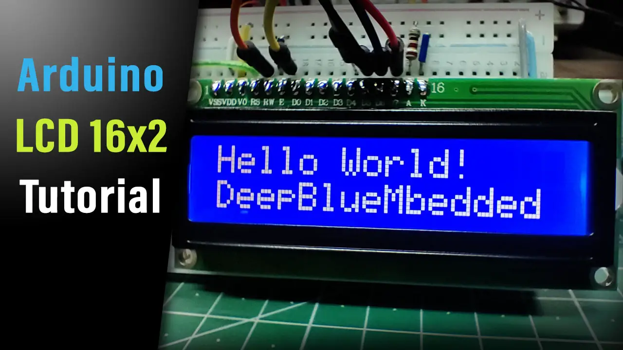
Now, let’s test what we’ve learned so far about the Arduino LCD and create our first project to display some text messages on the LCD display. On the first row of the LCD, we’ll print the “Hello World!” message. And we’ll move the cursor to the second row and write a “DeepBlueMbedded” text message.
Arduino LCD Text Display Example
In this first example, we’ll include the Arduino’s LiquidCrystal library and use it to display some text messages on the LCD 16×2 display.
Wiring
Here is how to hook up the LCD 16×2 display to the Arduino UNO board.
Example Code
Here is the full code listing for this example.
|
1 2 3 4 5 6 7 8 9 10 11 12 13 14 15 16 17 18 19 20 21 22 23 24 25 26 |
/* * LAB Name: Arduino LCD 16x2 Text Example * Author: Khaled Magdy * For More Info Visit: www.DeepBlueMbedded.com */ #include <LiquidCrystal.h> LiquidCrystal MyLCD(12, 11, 5, 4, 3, 2); // Creates an LCD object, Parameters: (RS, EN, D4, D5, D6, D7) void setup() { MyLCD.begin(16, 2); // Set up the number of columns and rows on the LCD. // Move The Cursor To Char:1,Line:1 MyLCD.setCursor(0, 0); // Print The First Message MyLCD.print("Hello World!"); // Move The Cursor To Char:1,Line:2 MyLCD.setCursor(0, 1); // Print The Second Message MyLCD.print("DeepBlueMbedded"); } void loop() { // DO NOTHING } |
Code Explanation
First of all, we need to include the Arduino LiquidCrystal.h library which we’ll be using to control the LCD driver.
|
1 |
#include <LiquidCrystal.h> |
Next, we’ll create an object of the LiquidCrystal class and define its parameters. The parameters for the LiquidCrystal object are the pin numbers for the following signals: RS, EN, D4, D5, D5, D7. If you want to add another LCD, you’ll have to create another object with another 6 IO pins for its signals.
|
1 |
LiquidCrystal MyLCD(12, 11, 5, 4, 3, 2); // Creates an LCD object, Parameters: (RS, EN, D4, D5, D6, D7) |
setup()
in the setup() function, we initialize the LCD object ( MyLCD) using the .begin() function. Which takes only 2 parameters (number of columns, and number of rows). For 16×2 LCD, we call MyLCD.begin(16, 2); For 20×4 LCD, we call MyLCD.begin(20, 4); And so on.
|
1 |
MyLCD.begin(16, 2); // Set up the number of columns and rows on the LCD. |
Then, we set the LCD cursor position to point to the first line, the first character cell. Any write operation to the LCD will start from the current cursor position value, that’s why it’s important to set it manually before attempting any write operation. This is to make sure that the text will be displayed exactly where we want it to be.
|
1 |
MyLCD.setCursor(0, 0); // (CharIndex, LineIndex) |
There are 2 rows and 16 columns in our LCD as we’ve stated earlier. The cursor index value starts from 0, therefore, the first row has an index of 0, and the second row has an index of 1. And this is also the case for the columns’ index value which also starts from 0 up to 15.
Next, we’ll print the first text message "Hello World!" to the LCD starting from the current cursor position (0, 0). Using the .print() function.
|
1 |
MyLCD.print("Hello World!"); |
Similarly, we’ll point to the beginning of the second LCD line (row) and write the second message.
loop()
in the loop() function, nothing needs to be done.
Simulation
Here is the simulation result for this project on the TinkerCAD simulator.

You can check this simulation project on TinkerCAD using this link.
Testing Results
Here is the result of testing this project code example on my Arduino UNO board.

Arduino 16×2 LCD Display Variables Example
In this example, we’ll print numeric variables to the LCD display. We’ll create a counter variable and print it to the LCD using the same .print() function. Which can also accept a lot of variable data types (strings, integers, float, double, etc). So luckily, we won’t be in need to do string manipulations and data type conversion to achieve the goals of this example project.
Wiring
Exactly the same as the previous example project.
Example Code
Here is the full code listing for this example.
|
1 2 3 4 5 6 7 8 9 10 11 12 13 14 15 16 17 18 19 20 21 22 23 |
/* * LAB Name: Arduino LCD 16x2 Variable Display * Author: Khaled Magdy * For More Info Visit: www.DeepBlueMbedded.com */ #include <LiquidCrystal.h> uint16_t Counter = 0; LiquidCrystal MyLCD(12, 11, 5, 4, 3, 2); // Creates an LCD object, Parameters: (RS, EN, D4, D5, D6, D7) void setup() { MyLCD.begin(16, 2); // Set up the number of columns and rows on the LCD. MyLCD.setCursor(0, 0); MyLCD.print("Counter Value:"); } void loop() { MyLCD.setCursor(0, 1); MyLCD.print(Counter++); delay(250); } |
Code Explanation
First of all, we need to include the Arduino LiquidCrystal.h library which we’ll be using to control the LCD driver.
|
1 |
#include <LiquidCrystal.h> |
Next, we’ll create an object of the LiquidCrystal class and define its parameters. The parameters for the LiquidCrystal object are the pin numbers for the following signals: RS, EN, D4, D5, D5, D7. If you want to add another LCD, you’ll have to create another object with another 6 IO pins for its signals.
|
1 |
LiquidCrystal MyLCD(12, 11, 5, 4, 3, 2); // Creates an LCD object, Parameters: (RS, EN, D4, D5, D6, D7) |
setup()
in the setup() function, we initialize the LCD object ( MyLCD) using the .begin() function.
|
1 |
MyLCD.begin(16, 2); // Set up the number of columns and rows on the LCD. |
Then, we set the LCD cursor position to point to the first line, the first character cell. Any write operation to the LCD will start from the current cursor position value, that’s why it’s important to set it manually before attempting any write operation. To make sure that the text will be displayed exactly where we want it to be.
|
1 |
MyLCD.setCursor(0, 0); // (CharIndex, LineIndex) |
Next, we’ll print the first text message "Counter Value:" to the LCD starting from the current cursor position (0, 0). Using the .print() function.
|
1 |
MyLCD.print("Counter Value:"); |
loop()
in the loop() function, we’ll point to the first character location on the second row (line) of the LCD. And write the Counter variable to the LCD using the .print() function.
|
1 |
MyLCD.print(Counter++); |
We also increment the Counter variable and insert a small time delay before repeating the same instructions over and over again.
Simulation
Here is the simulation result for this project on the TinkerCAD simulator.
You can check this simulation project on TinkerCAD using this link.
Testing Results
Here is the result of testing this project code example on my Arduino UNO board.
Arduino LCD Scrolling Text Example
In this example, we’ll print some text messages and shift the entire LCD display to create a text-scrolling effect. We’ll use the scrollDisplayLeft() and scrollDisplayRight() functions to create the scrolling effect.
The LCD’s internal Display data RAM (DDRAM) stores display data represented in 8-bit character codes. Its extended capacity is 80 × 8 bits or 80 characters. The area in display data RAM (DDRAM) that is not used for display can be used as general data RAM.
Therefore, whatever data you send to the DDRAM, it’ll get displayed on the LCD. As long as the characters count is below 32 (for 16×2 LCD), it’ll be visible. Otherwise, written characters are stored in the DDRAM but not visible.
Shifting the LCD display moves the data in the DDRAM in a circular way, when it reaches the end of the RAM space, you’ll find your text coming from the other LCD end. To test this, keep shifting the LCD text to the left maybe 100 times. When the buffer reaches the limit, you’ll find your text message coming from the right side of the LCD. Why? because it’s circulating through the DDRAM.
Wiring
Exactly the same as the previous example project.
Example Code
Here is the full code listing for this example.
|
1 2 3 4 5 6 7 8 9 10 11 12 13 14 15 16 17 18 19 20 21 22 23 24 25 26 27 28 29 30 31 32 33 34 35 36 37 |
/* * LAB Name: Arduino LCD 16x2 Scrolling Text * Author: Khaled Magdy * For More Info Visit: www.DeepBlueMbedded.com */ #include <LiquidCrystal.h> // Create An LCD Object. Signals: [ RS, EN, D4, D5, D6, D7 ] LiquidCrystal MyLCD(12, 11, 5, 4, 3, 2); void setup() { // Initialize The LCD. Parameters: [ Columns, Rows ] MyLCD.begin(16, 2); // Display The First Message In Home Position (0, 0) MyLCD.print(" Arduino LCD"); // Display The Second Message In Position (0, 1) MyLCD.setCursor(0, 1); MyLCD.print("DeepBlueMbedded"); } void loop() { // Shift The Entire Display To Right 10 Times for(int i=0; i<10; i++) { MyLCD.scrollDisplayRight(); delay(350); } // Shift The Entire Display To Left 10 Times for(int i=0; i<10; i++) { MyLCD.scrollDisplayLeft(); delay(350); } } |
Code Explanation
First of all, we need to include the Arduino LiquidCrystal.h library which we’ll be using to control the LCD driver.
|
1 |
#include <LiquidCrystal.h> |
Next, we’ll create an object of the LiquidCrystal class and define its parameters. The parameters for the LiquidCrystal object are the pin numbers for the following signals: RS, EN, D4, D5, D5, D7. If you want to add another LCD, you’ll have to create another object with another 6 IO pins for its signals.
|
1 |
LiquidCrystal MyLCD(12, 11, 5, 4, 3, 2); // Creates an LCD object, Parameters: (RS, EN, D4, D5, D6, D7) |
setup()
in the setup() function, we initialize the LCD object ( MyLCD) using the .begin() function.
|
1 |
MyLCD.begin(16, 2); // Set up the number of columns and rows on the LCD. |
Then, we set the LCD cursor position to point to the first line, the first character cell. Any write operation to the LCD will start from the current cursor position value, that’s why it’s important to set it manually before attempting any write operation. To make sure that the text will be displayed exactly where we want it to be.
|
1 |
MyLCD.setCursor(0, 0); // (CharIndex, LineIndex) |
Next, we’ll print the first text messages " Arduino LCD " and “ DeepBlueMbedded” to the LCD on lines 1 and 2 respectively. Using the .print() function.
|
1 2 3 4 |
MyLCD.print(" Arduino LCD"); // Display The Second Message In Position (0, 1) MyLCD.setCursor(0, 1); MyLCD.print("DeepBlueMbedded"); |
loop()
in the loop() function, we’ll shift the entire display to the right side 10 times using a for loop and the scrollDisplayRight() function from the LCD LiquidCrystal library. The inserted delay here is to allow us to see the scrolling effect, and you can definitely change it to make the scrolling effect even faster or slower.
|
1 2 3 4 5 |
for(int i=0; i<10; i++) { MyLCD.scrollDisplayRight(); delay(350); } |
Next, we’ll repeat the same step but the shifting will be in the opposite direction (left) and the code logic will be repeated forever.
Simulation
Here is the simulation result for this project on the TinkerCAD simulator.
You can check this simulation project on TinkerCAD using this link.
Testing Results
Here is the result for testing this project code example on my Arduino UNO board.
Arduino LCD Custom Character Generation & Display
In this example project, we’ll create some custom characters (emojis and icons) and send them to the LCD display. It has an internal CGRAM that can hold up to 8 custom characters at maximum and you’ll learn how to use it in this example project.
The LCD has an internal Character Generator ROM (CGROM). The character generator ROM generates (5×8) dots or (5×10) dot character patterns from 8-bit character codes. It can generate 208 (5×8) dot character patterns and 32 (5×10) dot character patterns. User-defined character patterns are also available by mask-programmed ROM.
Given that the CGROM has 208 character patterns for (5×8) dot displays, this means that not all the 255 ASCII table characters are available by default in the LCD display. You can refer to this tutorial for more information about this. As we’re more interested in the LCD’s internal CGRAM.
In the Character Generator RAM (CGRAM), the user can write new custom character patterns. For (5×8) dots display, eight-character patterns can be written at maximum. Only 8 custom character seems like a small space but it’s what it’s and we’ll see how to use it in this example project.
Arduino LCD Custom Character Generator
You can use this online LCD Custom Character Generator Tool and it’ll give you the Arduino C-Code for it, which you can easily copy and paste into your project code. And here is how to use it:
Click on the pixels to draw your custom LCD character, you can invert or clear the entire display cell if you want with the buttons below. If you’re satisfied with how your icon/emoji looks, you can copy the code and you’re good to go. Here are some example custom characters generated by this tool.

I used my custom LCD character generator tool to create the above icons/emojis (heart, speaker, smiley face, notification bell, battery level indicator). We’ll display all of those icons in this example project to show you how it’s done in Arduino code.
Wiring
Exactly the same as the previous example projects.
Example Code
Here is the full code listing for this example.
|
1 2 3 4 5 6 7 8 9 10 11 12 13 14 15 16 17 18 19 20 21 22 23 24 25 26 27 28 29 30 31 32 33 34 35 36 37 38 39 40 41 42 43 44 45 46 47 48 49 50 51 52 53 54 55 56 57 58 |
/* * LAB Name: Arduino LCD 16x2 Custom Characters Display * Author: Khaled Magdy * For More Info Visit: www.DeepBlueMbedded.com */ #include <LiquidCrystal.h> // Create An LCD Object. Signals: [ RS, EN, D4, D5, D6, D7 ] LiquidCrystal MyLCD(12, 11, 5, 4, 3, 2); // LCD Custom Characters uint8_t HeartChar[] = {0x00, 0x00, 0x0a, 0x15, 0x11, 0x0a, 0x04, 0x00}; uint8_t SpeakerChar[] = {0x01, 0x03, 0x07, 0x1f, 0x1f, 0x07, 0x03, 0x01}; uint8_t SmileyFaceChar[] = {0x00, 0x00, 0x0a, 0x00, 0x1f, 0x11, 0x0e, 0x00}; uint8_t BellChar[] = {0x04, 0x0e, 0x0a, 0x0a, 0x0a, 0x1f, 0x00, 0x04}; uint8_t Battery1Char[] = {0x0e, 0x1b, 0x11, 0x11, 0x11, 0x11, 0x11, 0x1f}; uint8_t Battery2Char[] = {0x0e, 0x1b, 0x11, 0x11, 0x11, 0x11, 0x1f, 0x1f}; uint8_t Battery3Char[] = {0x0e, 0x1b, 0x11, 0x11, 0x11, 0x1f, 0x1f, 0x1f}; uint8_t Battery4Char[] = {0x0e, 0x1b, 0x11, 0x1f, 0x1f, 0x1f, 0x1f, 0x1f}; void setup() { // Initialize The LCD. Parameters: [ Columns, Rows ] MyLCD.begin(16, 2); // Send The Custom Characters To LCD's CGRAM MyLCD.createChar(0, HeartChar); MyLCD.createChar(1, SpeakerChar); MyLCD.createChar(2, SmileyFaceChar); MyLCD.createChar(3, BellChar); MyLCD.createChar(4, Battery1Char); MyLCD.createChar(5, Battery2Char); MyLCD.createChar(6, Battery3Char); MyLCD.createChar(7, Battery4Char); // Clear The LCD Dispaly MyLCD.clear(); MyLCD.print("Custom Characters:"); // Print The Custom Characters MyLCD.setCursor(0, 1); MyLCD.write(byte(0)); MyLCD.setCursor(2, 1); MyLCD.write(byte(1)); MyLCD.setCursor(4, 1); MyLCD.write(byte(2)); MyLCD.setCursor(6, 1); MyLCD.write(byte(3)); MyLCD.setCursor(8, 1); MyLCD.write(byte(4)); MyLCD.setCursor(10, 1); MyLCD.write(byte(5)); MyLCD.setCursor(12, 1); MyLCD.write(byte(6)); MyLCD.setCursor(14, 1); MyLCD.write(byte(7)); } void loop() { // DO NOTHING! } |
Code Explanation
First of all, we need to include the Arduino LiquidCrystal.h library which we’ll be using to control the LCD driver.
|
1 |
#include <LiquidCrystal.h> |
Next, we’ll create an object of the LiquidCrystal class and define its parameters. The parameters for the LiquidCrystal object are the pin numbers for the following signals: RS, EN, D4, D5, D5, D7. If you want to add another LCD, you’ll have to create another object with another 6 IO pins for its signals.
|
1 |
LiquidCrystal MyLCD(12, 11, 5, 4, 3, 2); // Creates an LCD object, Parameters: (RS, EN, D4, D5, D6, D7) |
We’ll also define the byte array for the 8 custom characters that we’ve previously generated using the online tool.
|
1 2 3 4 5 6 7 8 9 |
// LCD Custom Characters uint8_t HeartChar[] = {0x00, 0x00, 0x0a, 0x15, 0x11, 0x0a, 0x04, 0x00}; uint8_t SpeakerChar[] = {0x01, 0x03, 0x07, 0x1f, 0x1f, 0x07, 0x03, 0x01}; uint8_t SmilyFaceChar[] = {0x00, 0x00, 0x0a, 0x00, 0x1f, 0x11, 0x0e, 0x00}; uint8_t BellChar[] = {0x04, 0x0e, 0x0a, 0x0a, 0x0a, 0x1f, 0x00, 0x04}; uint8_t Battery1Char[] = {0x0e, 0x1b, 0x11, 0x11, 0x11, 0x11, 0x11, 0x1f}; uint8_t Battery2Char[] = {0x0e, 0x1b, 0x11, 0x11, 0x11, 0x11, 0x1f, 0x1f}; uint8_t Battery3Char[] = {0x0e, 0x1b, 0x11, 0x11, 0x11, 0x1f, 0x1f, 0x1f}; uint8_t Battery4Char[] = {0x0e, 0x1b, 0x11, 0x1f, 0x1f, 0x1f, 0x1f, 0x1f}; |
setup()
in the setup() function, we initialize the LCD object ( MyLCD) using the .begin() function.
|
1 |
MyLCD.begin(16, 2); // Set up the number of columns and rows on the LCD. |
Then, we send the 8 custom characters byte-arrays to the LCD to be stored in its CGRAM memory.
|
1 2 3 4 5 6 7 8 9 |
// Send The Custom Characters To LCD's CGRAM MyLCD.createChar(0, HeartChar); MyLCD.createChar(1, SpeakerChar); MyLCD.createChar(2, SmilyFaceChar); MyLCD.createChar(3, BellChar); MyLCD.createChar(4, Battery1Char); MyLCD.createChar(5, Battery2Char); MyLCD.createChar(6, Battery3Char); MyLCD.createChar(7, Battery4Char); |
Next, we’ll clear the entire LCD display screen before writing. This step also moves the cursor to the home position (0, 0).
|
1 |
MyLCD.clear(); |
And finally, we’ll print the LCD custom characters. This is not a usual print command, it’s a command for the LCD to print the custom character saved in a specific location in the CGRAM memory. The following line of code tells the LCD to print the custom character saved in the CGRAM address location 0.
|
1 |
MyLCD.write(byte(0)); |
And similarly, we’ll do the same for the rest of the custom characters saved in the CGRAM address location 0 up to 7.
loop()
in the loop() function, nothing needs to be done.
Simulation
Here is the simulation result for this project on the TinkerCAD simulator.

You can check this simulation project on TinkerCAD using this link.
Testing Results
Here is the result of testing this project code example on my Arduino UNO board.

Arduino LiquidCrystal Library Useful Function
Here is a summarized list for the most important and useful functions in the LCD LiquidCrystal.h library that you’d need to use in your Arduino projects.
| LiquidCrystal Library Function | Function Description | |
| lcd.begin(cols, rows); | Initializes the interface to the LCD screen, and specifies the dimensions (width and height) of the display. the .begin() function needs to be called before any other LCD library commands. | |
| lcd.clear(); | Clears the LCD screen and points the cursor to the home position (in the upper-left corner). | |
| lcd.home(); | Sets the cursor to the home position (in the upper-left of the LCD) without clearing the text on the display. | |
| lcd.setCursor(col, row); | Position the LCD cursor to a desired location. | |
| lcd.noCursor(); | Hides the LCD cursor. | |
| lcd.cursor(); | Display the LCD cursor if it has been hidden. | |
| lcd.blink(); | Display the blinking LCD cursor. If used in combination with the cursor() function, the result will depend on the particular display device. | |
| lcd.noBlink(); | Turns off the blinking LCD cursor. | |
| lcd.noDisplay(); | Turns off the LCD display, without losing the text currently shown on it. This can be done to save some power if needed. | |
| lcd.display(); | Turns on the LCD display, after it’s been turned off with the noDisplay() function. This will restore the text (and cursor) that was on the display. | |
| lcd.scrollDisplayLeft(); |
Scrolls the contents of the display (text and cursor) one space to the left. |
|
| lcd.scrollDisplayRight(); |
Scrolls the contents of the display (text and cursor) one space to the right. |
|
| lcd.autoscroll(); |
Turns on automatic scrolling of the LCD. This causes each character output to the display to push previous characters over by one space. If the current text direction is left-to-right (the default), the display scrolls to the left; if the current direction is right-to-left, the display scrolls to the right. This has the effect of outputting each new character to the same location on the LCD. |
|
| lcd.noAutoscroll(); |
Turns off the automatic scrolling feature of the LCD. |
|
| lcd.leftToRight(); |
Set the direction for text written to the LCD to left-to-right, the default. This means that subsequent characters written to the display will go from left to right, but does not affect previously-output text. |
|
| lcd.rightToLeft(); |
Set the direction for text written to the LCD to right-to-left (the default is left-to-right). This means that subsequent characters written to the display will go from right to left, but does not affect previously-output text. |
|
You can also refer to Arduino’s official LiquidCrystal library page for more information and examples of the available APIs (functions) in this library.
Arduino 16×2 LCD Common Issues Troubleshooting
In this section, we’ll discuss some of the most common Arduino 16×2 LCD interfacing issues and how to troubleshoot those issues if you’re facing any of them in your project.
Garbage Characters Display
If your LCD is displaying garbage characters, it’s a strong indicator that there is an issue with data communication between your Arduino board and the LCD module itself. Make sure your connections are correct and the pin numbers for wiring are matching the software configurations that you’ve set in code like this.
|
1 |
LiquidCrystal MyLCD(12, 11, 5, 4, 3, 2); // Creates an LCD object, Parameters: (RS, EN, D4, D5, D6, D7) |
LCD Showing Black Boxes or Blank Display
This can be a contrast issue at the Vo pin, so make sure you’re connecting the contrast control potentiometer and turn it to the right and left until it’s properly set to an acceptable level.
Contrast is Ok, But Still Blank Display
This can be a power supply issue, make sure you’re connected to a stable +5v power supply. Sometimes powering from a USB port in a computer can cause power issues like this, so try using a power bank or a proper power supply and check if the issue is still persistent.
Using a poor power supply USB port, poor quality USB cables or even USB extender cables can cause all sorts of power issues. And the LCD display module is sensitive to such issues that you’d not detect during LEDs and buttons example projects.
Parts List
Here is the full components list for all parts that you’d need in order to perform the practical LABs mentioned here in this article and for the whole Arduino Programming series of tutorials found here on DeepBlueMbedded. Please, note that those are affiliate links and we’ll receive a small commission on your purchase at no additional cost to you, and it’d definitely support our work.
Download Attachments
You can download all attachment files for this Article/Tutorial (project files, schematics, code, etc..) using the link below. Please consider supporting my work through the various support options listed in the link down below. Every small donation helps to keep this website up and running and ultimately supports our community.
Wrap Up
To conclude this tutorial, we can say that the Arduino LiquidCrystal library eases the process of interfacing Arduino with LCD 16×2 display modules. You can even use it with different sizes of LCD displays like 16×4 or 20×4. This tutorial is a fundamental part of our Arduino Series of Tutorials because we’ll use it in so many tutorials and projects hereafter. So make sure, you’ve learned all the concepts and implemented the practice examples whether on your Arduino board or at least in the simulation environment.
If you’re just getting started with Arduino, you need to check out the Arduino Getting Started [Ultimate Guide] here.
And follow this Arduino Series of Tutorials to learn more about Arduino Programming.

This is the ultimate guide for getting started with Arduino for beginners. It’ll help you learn the Arduino fundamentals for Hardware & Software and understand the basics required to accelerate your learning journey with Arduino Programming.
It’s highly recommended to check out the Arduino I2C LCD interfacing tutorial linked below for more information about the I2C LCD module and how to use it with Arduino. There are so many examples right there which will definitely help you get the hang of it.

This is the ultimate guide for Arduino I2C LCD interfacing. Check it out to learn how the I2C LCD module works, how to use the LiquidCrystal_I2C library function to control it, change the I2C device address, connect multiple LCDs with Arduino using only 2 pins, and much more.
FAQ & Answers
You first need to follow the connection diagram between the Arduino board and the LCD module pins. Then, you need to include the Arduino LiquidCrystal library to drive the LCD. First, you need to include the library and create an object with your pin mapping configuration. Then, you’ll be able to write, clear, or shift the LCD display using the provided API (functions) in the LiquidCrystal library.
You don’t need to communicate with the LCD’s Hitachi HD44780 driver from scratch. Just use the Arduino built-in LiquidCrystal.h library which will handle the HD44780 driver communication to send data and commands on your behalf. First, you need to include the library and create an object with your pin mapping configuration. Then, you’ll be able to write, clear, or shift the LCD display using the provided API (functions) in the LiquidCrystal library.
The LCD 16×2 is used in so many Arduino projects as an output device that we typically use to display alphanumeric (text + number) messages to the end user. It can display temperature value, humidity, time, and any sort of data that can be displayed in a text or numeric format.